
Screw rotor with variable pitch and variable meshing clearance

A technology of variable meshing clearance and variable pitch, applied in rotary piston pumps, rotary piston machines, rotary piston/oscillating piston pump components, etc. Unstable, liquid hammer and other problems, to solve the pressure surge or even liquid hammer, increase safety and reliability, and improve volumetric efficiency.

Inactive Publication Date: 2017-02-15
CHINA UNIV OF PETROLEUM (EAST CHINA)
View PDF9 Cites 5 Cited by
  • Summary
  • Abstract
  • Description
  • Claims
  • Application Information

AI Technical Summary

Problems solved by technology

The volume of the former compression chamber is constant and there is no internal compression process. At the beginning of the discharge process of this twin-screw type gas-liquid mixed pump, the gas-liquid in the discharge pipe is introduced back into the compression chamber and is combined with the gas-liquid medium in the compression chamber. Mixing, the pressurization process is not stable, the pressure of the gas-liquid medium in each compression chamber rises unevenly, there is a sudden change in pressure, and it is easy to generate large shock vibration, which has high power consumption and low work efficiency
The latter has an internal compression process, that is, the compression chamber formed by the screw rotor is gradually reduced. When the liquid content of the gas-liquid medium conveyed by this twin-screw type gas-liquid mixed pump is high, due to the incompressibility of the liquid , the pressure in the compression chamber is prone to sudden increase, or even liquid shock, which affects the safe operation of the twin-screw gas-liquid mixed pump

Method used


Image

  • Screw rotor with variable pitch and variable meshing clearance
  • Screw rotor with variable pitch and variable meshing clearance
  • Screw rotor with variable pitch and variable meshing clearance

Examples


Embodiment Construction

[0039] The present invention will be further described below in conjunction with the accompanying drawings and embodiments.

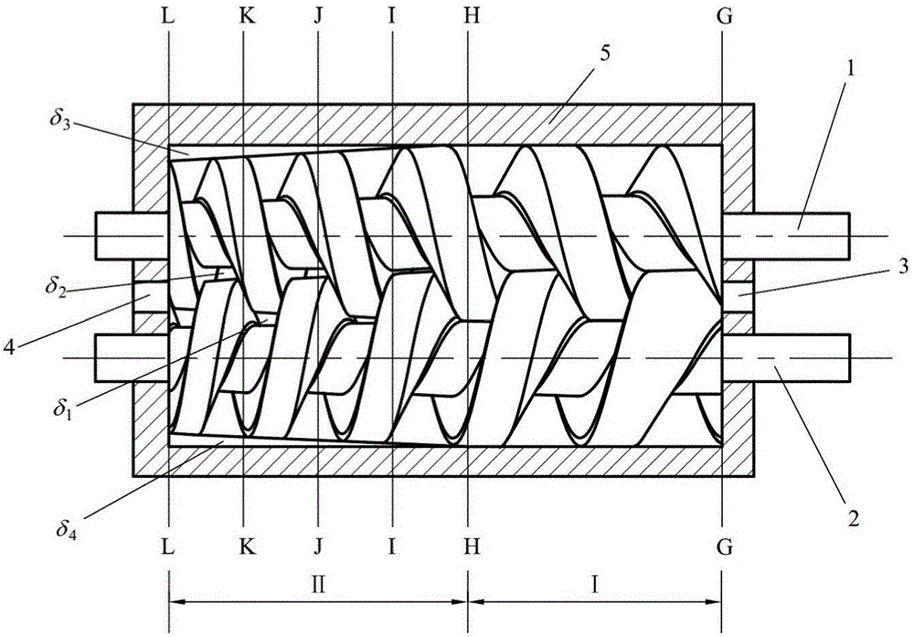
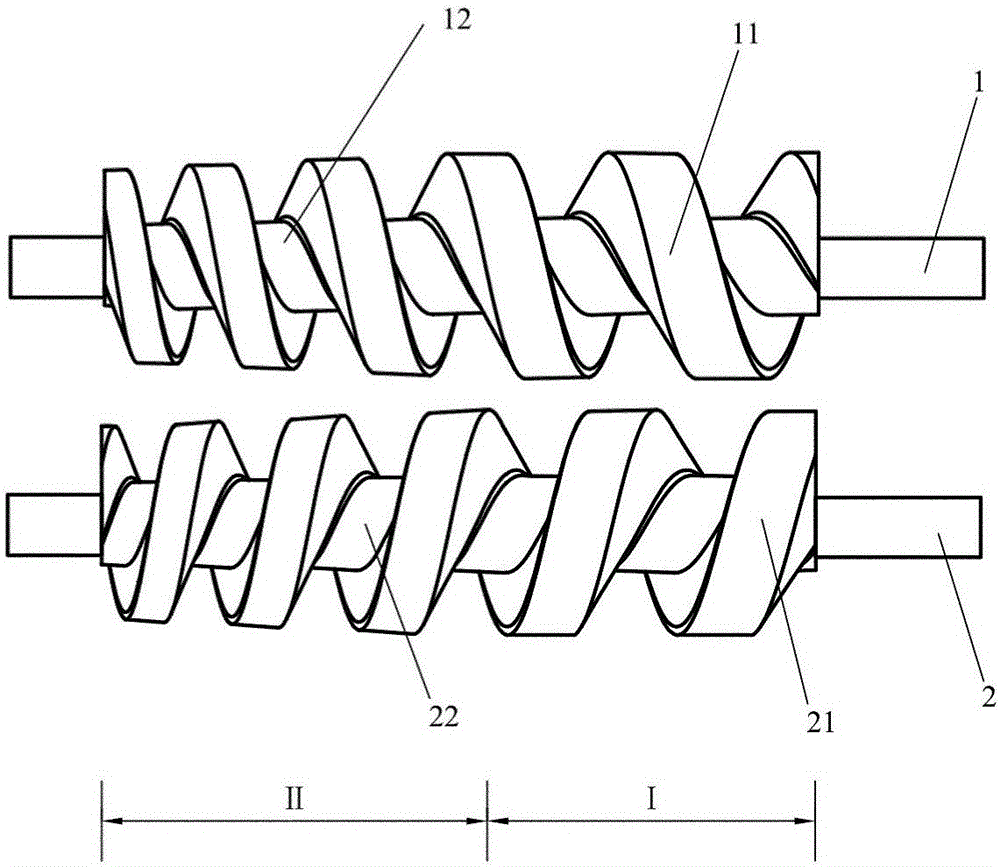
[0040] Such as figure 1 As shown, it is the meshing diagram of the screw rotor with variable pitch and variable meshing gap in operation; the right-handed screw rotor (1) and the left-handed screw rotor (2) that mesh with each other during work are both variable-pitch screw rotors, in the shell ( 5) to achieve meshing; the screw rotor is composed of a suction section (I) and a compression discharge section (II), and the two sections are smoothly connected; the suction section (I) of the screw rotor is connected to the suction port (3), and the compression discharge section ( Ⅱ) Connect the discharge port (4); the suction section (I) of the two screw rotors has no meshing clearance; the compression discharge section (II) of the two screw rotors has meshing clearance and is conical, the closer to the discharge section At the exit (4), the outer diameter ...


PUM


Abstract

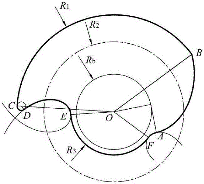
The invention provides a screw rotor with a variable pitch and a variable meshing clearance and a double-screw type gas-liquid mixture pump. The screw rotor is composed of a suction section (I) and a compression discharge section (II), wherein the molded line of the cross section of the suction section (I) is kept unchanged, so that zero-clearance meshing is realized; the molded line of the cross section of the compression discharge section (II) is variable, so that clearance meshing is realized, and the meshing clearance is greatly increased; and in any axial position, the molded line of the axial cross section of the screw rotor comprises six curves and one point. Internal compression is generated by the variable pitch, so that the pressurization process of gas-liquid media is stable; the screw rotor adopts the variable meshing clearance, so that a pressure relief channel from a compression chamber to the direction of an outlet is formed during operation; and in a gas-liquid mixed pressurization process, the volume of the compression chamber is gradually reduced, and a small quantity of gas-liquid media leak from the compression chamber to the outlet, so that random unloading of liquid-phase compression is realized, and the problems of pressure surge and liquid impact which are easily caused by incompressibility of liquid are solved.

Description

technical field [0001] The invention relates to a twin-screw type gas-liquid mixed delivery pump, in particular to a screw rotor with variable pitch and variable meshing clearance suitable for the twin-screw type gas-liquid mixed delivery pump. Background technique [0002] The gas-liquid multiphase mixed transportation technology with multiphase pump as the core has been widely used in the petroleum industry, especially for the development of marginal oil fields and satellite oil fields, which has significant economic benefits; the twin-screw gas-liquid mixed transportation pump relies on two screw rotors The mutual meshing between them realizes the periodic change of the volume of the working chamber to pressurize the gas-liquid medium to achieve the purpose of mixing gas-liquid mixed medium. According to the change law of the working chamber formed by the screw rotor, the existing twin-screw gas-liquid mixed pump can be divided into two types: the volume of the compressio...

Claims


Application Information

Patent Timeline
IPC IPC(8): F04C2/16F04C13/00F04C15/00
CPCF04C2/084F04C2/16F04C13/001F04C15/00F04C2250/20F04C2240/20
Inventor 王君黄松王安振黄译民张凌宏王鑫鑫祝玉婷
Owner CHINA UNIV OF PETROLEUM (EAST CHINA)
Learn More