Arrangement method of hobs for directly cutting reinforcements in concrete in shield tunneling machine
A layout method and shield machine technology, applied in the field of shield machines, can solve the problems of short steel bars and long steel bars stuck to the cutterhead screw conveyor, etc., so as to avoid being stuck, good economic and social benefits, and ensure normal operation The effect of excavation
- Summary
- Abstract
- Description
- Claims
- Application Information
AI Technical Summary
Problems solved by technology
Method used
Image

Examples
Embodiment 1
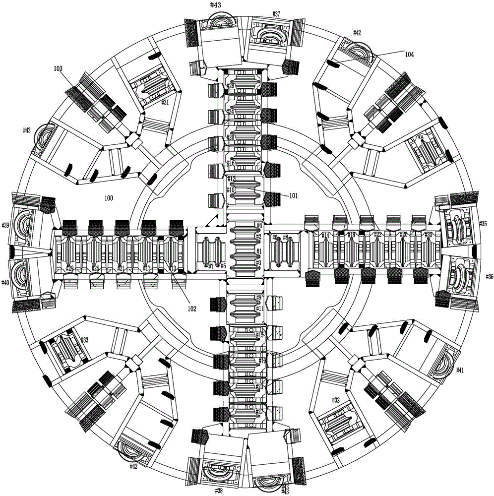
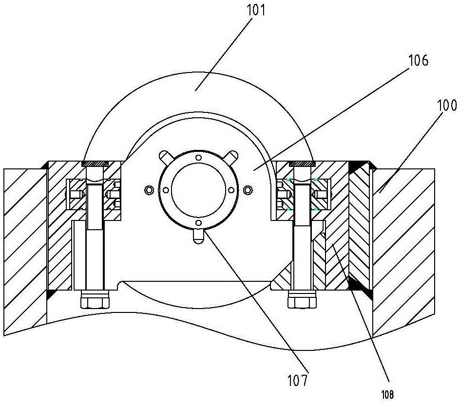
[0034] Such as figure 2 , Figure 4 and Figure 6 As shown, the end cover 106 of the knife box of the double-edged hob numbered #5 and #7 is heightened, and the center line of the center hole of the bearing 107 used to install the double-edged hob in the end cover 106 is raised by 20mm , that is to remake the end cover 106 after the central hole is raised by 20mm, and then install the end cover 106 together with the double-edged hob 101 in the knife box 108 numbered #5 and #7, so that the number after the heightening treatment is # 5 and #7 double-edged hobs had their cutting edges in the second plane.
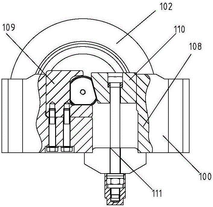
[0035] Such as image 3 , Figure 5 and Figure 6 As shown, the cutter boxes 108 of the single-edged hobs numbered #13, #18, #23, #28, and #32 remain unchanged, and the C-shaped block used to fix the single-edged hob 102 and the cutter box 108 109. Wedging block 110 and tension bolt 111 are heightened. The height of heightening is to increase the center line of single-e...
Embodiment 2
[0037]This embodiment is the basis for heightening the double-edged hobs numbered #5 and #7 and the single-edged hobs numbered #13, #18, #23, #28 and #32 in the above-mentioned first embodiment On the above, further heighten the double-edged hobs numbered #6 and #8, and the height of the raised height is to raise the center line of the double-edged hob by 40mm, so that the numbers after the heightened treatment are #6 and # The blade of the double-edged hob of 8 is in the third plane. Further, the double-edged hobs numbered #9 and #11 are also heightened, and the raised height is the same as that of the double-edged hobs numbered #5 and #7, so that the numbers are #5, #7 and #9 , #11 The blade of the double-edged hob is in the second plane.
[0038] The heightening method and height of the single-edged hobs numbered #13, #18, and #23 are the same as in the first embodiment above, and their blades are in the second plane. On this basis, they are numbered #15, # 20. Adjust the...
Embodiment 3
[0040] This embodiment is the same as the method of raising the height of the hob in the above embodiment, the difference is that the numbers of the hobs for the heightening treatment are different, specifically the blades of the double-edged hobs numbered #5 and #7 In the first plane, place the blades of the double-edged hobs numbered #4 and #6 in the third plane. Adjust the single-edged hobs numbered #21, #23, #29, #31 to the height of the blade in the second plane, adjust the single-edged hobs numbered #14, #22, #30 to the height of the blade The height is in the third plane. After the blades of all double-edged hobs and single-edged hobs are arranged in the same straight line, the height of the blade tip is still arranged in a "serrated" shape, such as Figure 8 shown.
[0041] It can be seen from the above examples that for the height adjustment of hobs, it is necessary to make all the hobs arranged in the order of numbering and the height of the knife tips be arranged ...
PUM
 Abstract
Description
Claims
Application Information
 - R&D
- Intellectual Property
- Life Sciences
- Materials
- Tech Scout
- Unparalleled Data Quality
- Higher Quality Content
- 60% Fewer Hallucinations
Browse by: Latest US Patents, China's latest patents, Technical Efficacy Thesaurus, Application Domain, Technology Topic, Popular Technical Reports.
© 2025 PatSnap. All rights reserved.Legal|Privacy policy|Modern Slavery Act Transparency Statement|Sitemap|About US| Contact US: help@patsnap.com