
Solar wing flexible simulator

A simulator and wing flexibility technology, applied in the aerospace field, can solve the problems of impossible, difficult frequency accurate simulation, inability to simulate different moments of inertia, etc., to achieve the effect of strong practicability and accurate simulation

Active Publication Date: 2017-02-15
HARBIN INST OF TECH +1
View PDF6 Cites 5 Cited by
  • Summary
  • Abstract
  • Description
  • Claims
  • Application Information

AI Technical Summary

Problems solved by technology

[0004] (1) The active simulator generates the required vibration form through the exciting parts, and its moment of inertia is almost unchanged when the vibration changes, so it cannot simulate the characteristics of different modes of spacecraft solar wings corresponding to different moments of inertia, and the simulation reliability is low
[0005] (2) The solar wing of the spacecraft has low stiffness, high modal order and dense low frequency. The existing simulators generally have small geometric dimensions and high modal frequencies, so it is difficult to achieve accurate simulation of frequency
In addition, there is no external resistance in the space environment, and the modal amplitude of each order of the solar wing is relatively large. The vibration of the existing simulator weakens rapidly with the modal order, and it is impossible to realize the true simulation of the modal amplitude of each order.
[0006] (3) In the actual test, it is often not necessary to pay attention to most of the modes of the solar wing, and it is only necessary to simulate the modes that have a greater impact on the system. The existing technology cannot provide the above-mentioned selective mode simulation
[0007] (4) In practical applications, it is often necessary to set the modal parameters such as torsion and bending separately, which cannot be realized by the existing technology

Method used


Image

  • Solar wing flexible simulator
  • Solar wing flexible simulator
  • Solar wing flexible simulator

Examples


Embodiment Construction

[0043] In order to make the objectives, technical solutions, and advantages of the present invention clearer and more comprehensible, the present invention will be further described in detail with reference to the accompanying drawings and preferred embodiments. However, it should be noted that many details listed in the specification are only to enable the reader to have a thorough understanding of one or more aspects of the present invention, and these aspects of the present invention can be implemented even without these specific details.

[0044] The inventor of the present invention considers that when a spacecraft is flying in orbit, it is prone to be affected by various propulsive forces to produce large vibrations. The coupling between the vibration of the flexible attachment and the motion of the spacecraft body will affect the attitude of the spacecraft. Stability and orientation accuracy have an impact, and even damage the instrument to invalidate the spacecraft. There...


PUM


Abstract

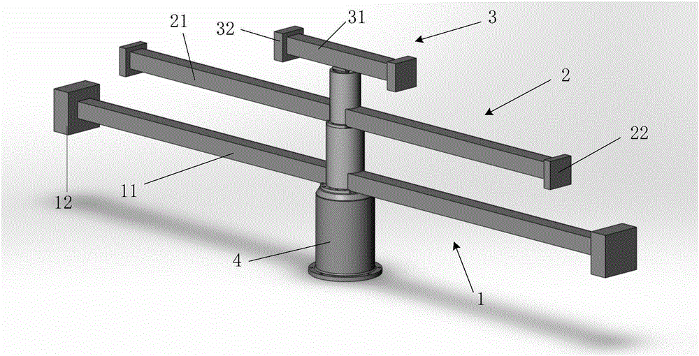
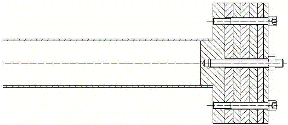
The invention discloses a solar wing flexible simulator. The solar wing flexible simulator comprises a base, a first simulating part, a second simulating part, a third simulating part and a torque sensor, wherein the first simulating part, the second simulating part and the third simulating part are sequentially connected and are installed on an air floating platform through the base connected with the first simulating part; the first simulating part is used for simulating the rotating inertia and the frequency of the first-order mode of a solar wing; the second simulating part is used for simulating the rotating inertia and the frequency of the sixth-order mode of the solar wing; the third simulating part is used for simulating the rotating inertia and the frequency of the twelfth-order mode of the solar wing; and the torque sensor is arranged at the position, close to the air floating platform, of the simulator and is used for measuring the torque output by the simulator to the air floating platform. The solar wing flexible simulator can analyze influences of different rotating inertias and different mode frequencies on a spacecraft body structure, and on the basis, the solar wing structure can be subjected to optimized design.

Description

Technical field [0001] The invention relates to the field of aerospace technology, in particular to a solar wing flexibility simulator. Background technique [0002] With the continuous increase in functions and complexity of modern spacecraft, flexible accessories such as large solar panels are also increasing. Because the flexible attachment is made of low-rigidity lightweight materials, the spacecraft is susceptible to various propulsive forces to produce large vibrations when flying in orbit. The vibration of the flexible attachment is coupled with the motion of the spacecraft body. It will affect the attitude stability and orientation accuracy of the spacecraft, and even damage the instrument and cause the spacecraft to fail. Therefore, it is of great significance to design a solar wing flexible simulator to conduct physical simulation experiments on the ground to study the influence of flexible accessories on the main structure of the spacecraft. [0003] The solar wing has...

Claims


Application Information

Patent Timeline
Patent Type & Authority Applications(China)
IPC IPC(8): B64G7/00G09B23/08
CPCB64G7/00G09B23/08
Inventor 马广程夏红伟王常虹李丹阳温奇咏
Owner HARBIN INST OF TECH
Learn More