Material taking device and material taking method
A technology of a reclaiming device and a lifting device, applied in the field of machinery, can solve the problems of product falling, small injection molding products, easy air leakage, etc., and achieve the effects of reducing the falling rate, easy operation and simple structure
- Summary
- Abstract
- Description
- Claims
- Application Information
AI Technical Summary
Problems solved by technology
Method used
Image
Examples
Embodiment 1
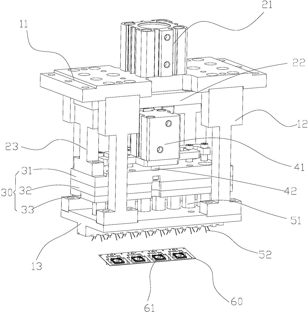
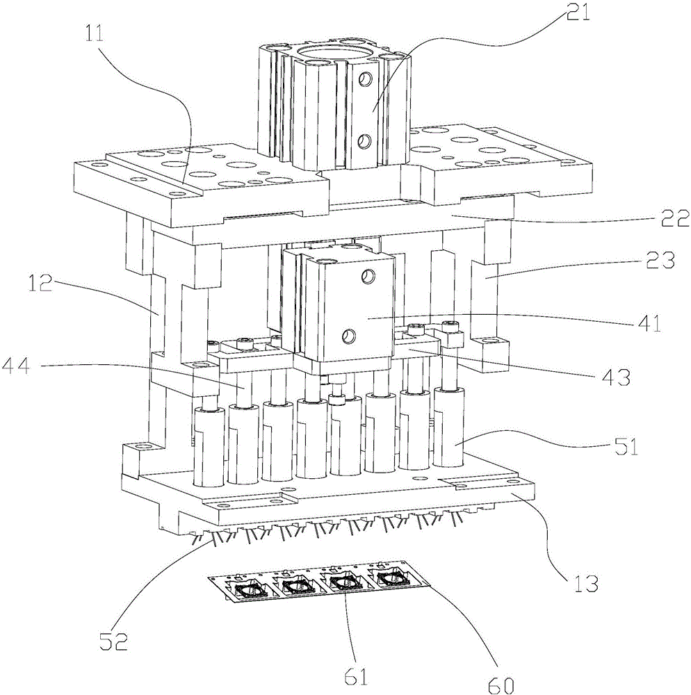
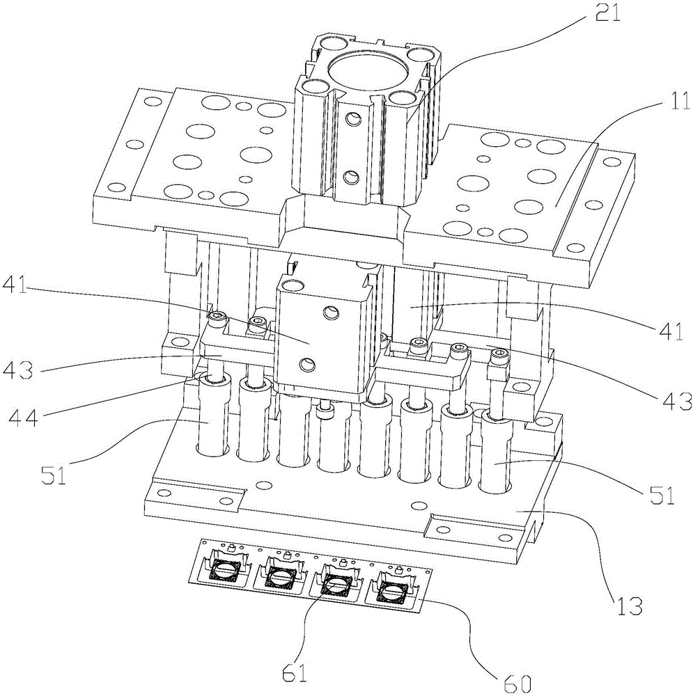
[0035] Reference Figure 1 to Figure 6 As shown, the reclaiming device provided by this embodiment includes: a body, a lifting mechanism, and eight sets of reclaiming components. The body consists of an upper panel 11, a lower panel 13, and a connection between the upper panel 11 and the lower panel 13. Consisting of four uprights 12, the reclaiming assembly includes: an abutment portion, a reclaiming head 51 and a claw provided with four claws 52. The claws 52 are long rod-shaped elastic bodies 52 with elastic self-restoring force. Fixedly arranged on the take-out head 51, the undeformed initial state of the multiple claws of the claws is an outwardly expanded structure in the shape of a "eight". In this embodiment, the material of the elastic body 52 is polyurethane. The parts are eight through holes 131 penetrating through the lower panel 13. The reclaiming head 51 of the reclaiming assembly is arranged in the body and corresponds to the positions of the through holes 131 one...
Embodiment 2
[0047] The structure of a material reclaiming device provided by this embodiment is substantially the same as that of the first embodiment. The only difference is that in this embodiment, the claws of the claws are inelastic and rigid, and the claws are all pivotally connected. On the reclaiming head 51, the multiple claws are formed into an outwardly expanded state by the elastic force of an elastic member (such as a spring or an elastic piece, etc.). During the ascending process of the claws, the multiple claws are The compression of the conflicting through holes compresses the elastic member to shrink inward, and the elastic force of the elastic member causes the plurality of pawls of the pawl to resume expansion outward during the descending process of the pawl. And then realize the reclaiming.
[0048] The disclosed elastic members and connection relationships added in this embodiment are all existing technologies, and those skilled in the art can easily grasp and implement ...
Embodiment 3
[0050] The structure of a reclaiming device provided by this embodiment is roughly the same as that of the first embodiment, the only difference is that reference Figure 7 As shown, in this embodiment, the abutting portion is an annular member 70 provided on the periphery of the claw portion 52 of the claw. The ring member 70 is connected to the driving end of the lifting mechanism, and the lifting mechanism drives the ring 70 and the claw For example, the lifting mechanism drives the ring member 70 to descend, and the lifting mechanism drives the claw to rise. At this time, the ring member 70 abuts against the claw portion 52 of the claw, and causes the claws of the claw to The portion 52 has an inner convergent structure, and then the lifting mechanism drives the ring member 70 up, and the lifting mechanism drives the claw down. At this time, the claw portion 52 of the claw separates from the ring member 70, and the elastic self-restoring force assumes an outwardly expanding s...
PUM
 Abstract
Description
Claims
Application Information
 - R&D
- Intellectual Property
- Life Sciences
- Materials
- Tech Scout
- Unparalleled Data Quality
- Higher Quality Content
- 60% Fewer Hallucinations
Browse by: Latest US Patents, China's latest patents, Technical Efficacy Thesaurus, Application Domain, Technology Topic, Popular Technical Reports.
© 2025 PatSnap. All rights reserved.Legal|Privacy policy|Modern Slavery Act Transparency Statement|Sitemap|About US| Contact US: help@patsnap.com


