Material taking gripper for bottle

A bottle and material grasping technology, which is applied in the field of bottle retrieving grippers, can solve problems such as potential safety hazards and bottle slippage, and achieve the effect of a firm structure of the retrieving gripper

Inactive Publication Date: 2016-12-14
TAICANG GOLDENMA METAL STRUCTURE
View PDF7 Cites 0 Cited by
  • Summary
  • Abstract
  • Description
  • Claims
  • Application Information

AI Technical Summary

Problems solved by technology

Since the outer diameters of the bottle mouth and the bottle neck are usually not much different, this method is prone to the phenomenon of bottle slippage, which has potential safety hazards

Method used


Image

  • Material taking gripper for bottle
  • Material taking gripper for bottle
  • Material taking gripper for bottle

Examples


Embodiment 1

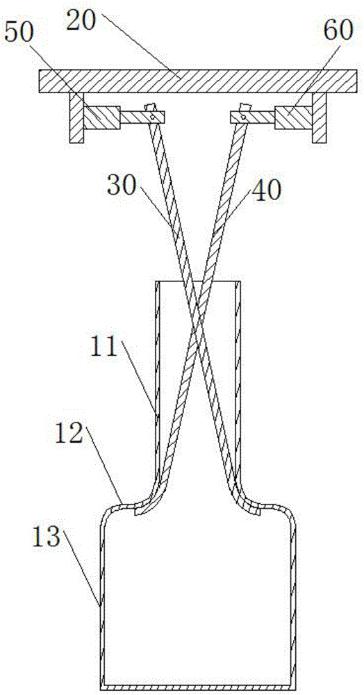
[0022] see figure 1 , as shown in the legend therein, a bottle retrieving gripper is used for retrieving the blown bottle product. The bottle includes a bottle neck 11, a bottle shoulder 12 and a bottle body 13. The first clamping rod 30 and the second clamping rod 40, the bottom of the top plate 20 is symmetrically installed with the first cylinder 50 and the second cylinder 60, the upper end of the first clamping rod 30 and the upper end of the second clamping rod 40 are opposite and connected respectively On the first cylinder 50 and the second cylinder 60, the lower end of the first clamping rod 30 is opposite to the lower end of the second clamping rod 40 and the two are respectively bent back to form a grapple matching the inner wall of the bottle shoulder 12, the first The cylinder 50 and the second cylinder 60 drive the first clamping rod 30 and the second clamping rod 40 respectively, so that the distance between the grapple free end of the first clamping rod 30 and t...

Embodiment 2

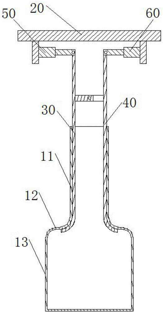
[0029] see figure 2 , as shown in the legend therein, the rest are the same as the first embodiment, the difference is that the first clamping rod 30 and the second clamping rod 40 are jointly connected on a shaft to form two lever structures, the first clamping rod 30 The upper end of the upper end and the upper end of the second clamping rod 40 are hingedly connected with the first air cylinder 50 and the second air cylinder 60 respectively.

[0030] The first clamping bar 30 and the second clamping bar 40 are substantially J-shaped respectively, and the two are arranged with their backs crossed. The lower end of the second clamping rod 40 is close, and the upper end of the first clamping rod 30 is far away from the upper end of the second clamping rod 40 so that the lower end of the first clamping rod 30 and the lower end of the second clamping rod 40 are separated.

Embodiment 3

[0032] see image 3 , as shown in the legend therein, the rest are the same as the second embodiment, the difference is that the first clamping rod 30 and the second clamping rod 40 are respectively substantially in the shape of a J, and the two are arranged with their backs facing each other, and the upper end of the first clamping rod 30 Close to the upper end of the second clamping bar 40 so that the lower end of the first clamping bar 30 and the lower end of the second clamping bar 40 are away from each other, and the upper end of the first clamping bar 30 and the upper end of the second clamping bar 40 are far away to make the first clamping bar The lower end of 30 is close to the lower end of the second clamping rod 40 .


PUM


Abstract

The invention discloses a material taking gripper for a bottle. The material taking gripper comprises a top plate, a first clamping rod and a second clamping rod, wherein a first drive component and a second drive component are symmetrically installed at the bottom of the top plate; the upper end of the first clamping rod and the upper end of the second clamping rod are opposite in position and are connected to the first drive component and the second drive component respectively; the lower end of the first clamping rod and the lower end of the second clamping rod are opposite in position and are oppositely bent respectively to form gripping hooks matched with the inner wall of a bottle shoulder; and the first drive component and the second drive component drive the first clamping rod and the second clamping rod respectively to enable a distance between the free end of the gripping hook of the first clamping rod and the free end of the gripping hook of the second clamping rod to be greater than the inner-diameter dimension of a bottle neck. The material taking gripper disclosed by the invention realizes material taking for the bottle through the arrangement of the first clamping rod, the second clamping rod, the first drive component and the second drive component, and through adjustment for the distance between the first clamping rod and the second clamping rod.

Description

technical field [0001] The invention relates to a bottle blowing machine, in particular to a bottle material picking gripper. Background technique [0002] When the bottles enter the filling system, they must be neatly arranged according to certain rules. The bottles blown out by the current linear blow molding machine are clamped by the bottle-discharging manipulator to carry out the bottle-discharging operation. The manipulator is composed of a pair of claws, and the opposite sides of the two claws are provided with grooves matching the bottle neck. When the blown bottle is sent to the grasping position of the manipulator, the two claws of the manipulator open , so that the bottleneck of the bottle enters the groove of the jaws, close the jaws to clamp the bottleneck for subsequent operations. Because the outer diameters of the bottle mouth and the bottle neck are usually not much different, this method is prone to the phenomenon that the bottle slips off, and there is a ...

Claims


Application Information

Patent Timeline
Patent Type & Authority Applications(China)
IPC IPC(8): B65B43/46
CPCB65B43/46
Inventor 马志刚陈伟
Owner TAICANG GOLDENMA METAL STRUCTURE
Why Eureka
Try Eureka