
Cleaning device for speed reducer bearing inner rings

A bearing inner ring and cleaning device technology, which is applied in the direction of mechanical equipment, engine components, engine lubrication, etc., can solve the problems of easy scratches on the surface of the bearing inner ring, deviation of the oil injection pipe from the cotton brush, scrapping of the inner ring of the bearing, etc. Achieve the effect of eliminating oil-free grinding, spraying oil evenly, and preventing scratches

Inactive Publication Date: 2017-02-15
PROFIT TRANSMISSION EQUIP YANCHENG CO LTD
View PDF0 Cites 1 Cited by
  • Summary
  • Abstract
  • Description
  • Claims
  • Application Information

AI Technical Summary

Problems solved by technology

The structure of the bearing mainly includes: the inner ring of the bearing and the inner ring of the bearing, the rolling elements and the cage that are rolled between the inner ring of the bearing and the inner ring of the bearing, and the surface of the inner ring of the bearing needs to be cleaned, ground and decontaminated during production. The oil injection pipe of the bearing inner ring cleaning device is placed in the air. During the cleaning process, the oil injection pipe tends to deviate from the cotton brush with its own gravity, resulting in no lubricating oil sprayed on the inner ring of the reducer bearing by the cotton brush when cleaning, grinding and decontamination. The surface of the inner ring of the bearing, the surface of the inner ring of the bearing is prone to scratches, which seriously affects the quality of the product, and even causes the inner ring of the bearing to be scrapped

Method used


Image

  • Cleaning device for speed reducer bearing inner rings

Examples


Embodiment Construction

[0008] The specific content of the present invention will be described in detail below in conjunction with the accompanying drawings and specific embodiments.

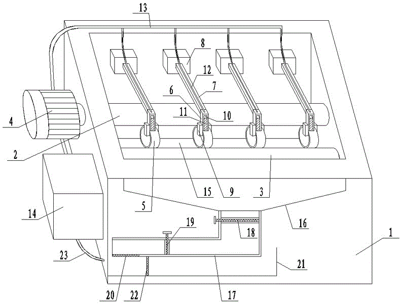
[0009] Such as figure 1 As shown, the cleaning device for the inner ring of the reducer bearing includes: a frame 1, a rotating shaft 2 and a supporting shaft 3 are arranged inside the frame 1, and one end of the rotating shaft 2 protrudes from the frame 1 to connect with the driving device 4 A number of bearing inner rings 5 ​​are evenly arranged between the rotating shaft 2 and the support shaft 3, and a cotton brush installation block 6 is arranged on the upper end of the bearing inner ring 5, and the cotton brush installation block 6 is connected with the adjustment bracket 7 The cotton brush installation block adjustment device 8 is connected, and the cotton brush installation block adjustment device 8 is arranged on the frame 1, and the bearing inner ring limit block 9 is arranged symmetrically on both sides of t...


PUM


Abstract

The invention discloses a cleaning device for speed reducer bearing inner rings. The cleaning device comprises a rack. A rotating shaft and a supporting shaft are arranged in the rack. One end of the rotating shaft stretches out of the rack and is connected with a drive device. The multiple bearing inner rings are evenly arranged between the rotating shaft and the supporting shaft. Cotton brush installing blocks are arranged at the upper ends of the bearing inner rings and connected with cotton brush installing block adjusting devices through adjusting supports. The cotton brush installing block adjusting devices are arranged on the rack. Bearing inner ring limiting blocks are symmetrically arranged on the two sides of each cotton brush installing block. Each bearing inner ring is clamped between the corresponding two bearing inner ring limiting blocks. Cotton brush installing grooves are formed in the cotton brush installing blocks. Cotton brushes matched with the bearing inner rings are arranged in the cotton brush installing grooves. Oil spraying branch pipes are arranged at the upper ends of the cotton brush installing blocks, and one ends of the oil spraying branch pipes communicate with the cotton brush installing grooves.

Description

technical field [0001] The invention relates to a bearing processing equipment, in particular to a cleaning device for the inner ring of a reducer bearing. Background technique [0002] The input shaft and output shaft inside the reducer need bearings for support, and the reducer bearing can start to reduce the load friction coefficient during the operation of the reducer. The structure of the bearing mainly includes: the inner ring of the bearing and the inner ring of the bearing, the rolling elements and the cage that are rolled between the inner ring of the bearing and the inner ring of the bearing, and the surface of the inner ring of the bearing needs to be cleaned, ground and decontaminated during production. The oil injection pipe of the bearing inner ring cleaning device is placed in the air. During the cleaning process, the oil injection pipe tends to deviate from the cotton brush with its own gravity, resulting in no lubricating oil sprayed on the inner ring of the...

Claims


Application Information

Patent Timeline
Patent Type & Authority Applications(China)
IPC IPC(8): B08B1/02B08B13/00F16N7/30F16N7/38
CPCF16N7/30F16N7/38B08B13/00B08B1/12B08B1/20
Inventor 张亦标董杰初
Owner PROFIT TRANSMISSION EQUIP YANCHENG CO LTD
Learn More