
Method for data conversion between stress analysis and three-dimensional models in pipeline design

A stress analysis and three-dimensional model technology, applied in the direction of electrical digital data processing, computer-aided design, special data processing applications, etc., can solve problems such as wasting time, increasing the error rate of calculation data input, reducing the quality of finished product design, etc., to achieve multiple solutions The effects of professional collaboration, reduction of repeated input, and improvement of design efficiency

Active Publication Date: 2017-02-08
四川电力设计咨询有限责任公司
View PDF6 Cites 13 Cited by
  • Summary
  • Abstract
  • Description
  • Claims
  • Application Information

AI Technical Summary

Problems solved by technology

[0004] (1) Every time the pipeline stress analysis model is adjusted, the 3D pipeline model needs to be manually established in the PDMS software, which involves a lot of repetitive work, wastes a lot of time, and greatly affects work efficiency
[0005] (2) In the process of re-establishing and modifying the 3D model, errors are prone to occur and details are easily lost, especially when the piping layout personnel and the 3D modeling personnel are not the same person, it is more likely to lead to low quality of the final design product and error rate high
[0006] (3) Due to the uncontrollability of the process, the data is easily modified and lost after multiple manual transfers, which affects the consistency of stress analysis and 3D model data, which is not conducive to version control and multi-person and multi-professional collaboration
[0007] (4) Due to the cumbersomeness of the process, the complexity of collaborative design for designers, especially designers of various small professions, is obviously increased, and the workload of each professional is increased
[0009] (1) There is a problem that the pipeline stress data file is inconsistent with the 3D model
[0010] (2) The workload of manually filling in the input file of pipeline stress analysis is heavy, and the designer needs to manually fill in the GLIF software input file according to the data of the PDMS 3D model, which involves a large amount of data format conversion
When the spatial direction of the pipeline in the PDMS 3D model is adjusted for various reasons, it is necessary to manually modify the input file of the pipeline stress analysis many times, which greatly increases the workload of the designer
[0011] (3) The quality of the finished design is low. Since the pipeline model in the PDMS software is not related to the manually filled pipeline stress analysis input file, errors will inevitably occur
Especially for complex multi-branch piping systems, due to the difference in the ability of designers, human factors increase the error rate of calculation data input, and repeated revisions will easily cause designers to focus on one thing and lose another, thus reducing the quality of finished product design
[0012] (4) The data reuse rate in the design process is low. The pipeline design includes 3D model data, stress input data, and pipeline stress calculation result data. data support
[0013] From this, it can be found that no matter what kind of pipeline design method, there are obvious shortcomings such as repeated data input, heavy workload, and high error rate, which cannot meet the requirements of improving design efficiency and quality.

Method used


Image

  • Method for data conversion between stress analysis and three-dimensional models in pipeline design
  • Method for data conversion between stress analysis and three-dimensional models in pipeline design
  • Method for data conversion between stress analysis and three-dimensional models in pipeline design

Examples


Embodiment 1

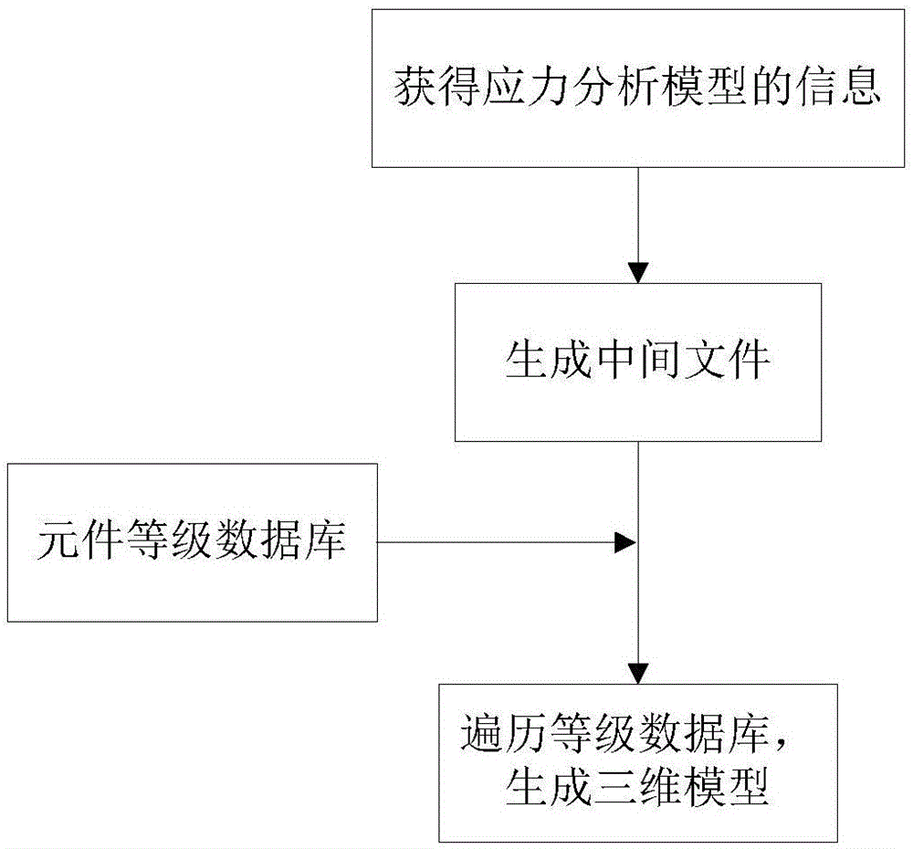
[0056] Such as figure 1 The data conversion method from stress analysis to three-dimensional model in the pipeline design of the present invention is shown, taking GLIF stress analysis software and PDMS three-dimensional model software as examples, the steps include:

[0057] A. Establish a stress analysis model that meets the stress requirements. By traversing the stress analysis model, obtain the pipeline topology, the spatial coordinates and interrelationships of each component, and component parameters including various levels of information. The obtained component parameters include multiple parts, first of all the grades of pipes, hangers and false tees that appear in the corresponding pipelines, and each grade is followed by temperature, pressure, material and corresponding in PDMS software Attributes such as class names. Then list all the branches in the pipeline and the related properties of all the pipe fittings under the branch in sequence according to the order of...

Embodiment 2

[0069] Such as Figure 9 In the shown pipeline design of the present invention, the data conversion method from three-dimensional model to stress analysis is taken as an example with PDMS three-dimensional model software and GLIF stress analysis software, and the steps include:

[0070] A. Use the grade name of the component as an index to establish a component grade database containing the parameters of each component. Different component grade names correspond to the corresponding data in the component grade database. The component grade database includes pipe wall thickness and outer diameter, pipe fitting weight, elbow bending radius and wall thickness, tee stress enhancement coefficient, large and small head outer diameter / small head outer diameter, pipe insulation under the corresponding grade name in the component grade database. Thickness, insulation layer bulk density and other parameter properties.

[0071] B. Establish the pipeline layout of the three-dimensional m...


PUM

PropertyMeasurementUnit
Outer diameteraaaaaaaaaa
Bending radiusaaaaaaaaaa

Abstract

The present invention relates to a method for data conversion between stress analysis and three-dimensional models in pipeline design. The method for data conversion from a stress analysis model to a three-dimensional model comprises: A. establishing a stress analysis model, and traversing the stress analysis model to obtain an element parameter that includes various level information; B. based on the obtained information, generating an immediate file according to a format that can be parsed by three-dimensional model software; C. establishing an element level database of the three-dimensional model software; and D.assigning a real level model to a corresponding branch and element according to a level of the immediate file, and generating a three-dimensional model in the three-dimensional model software. According to the method provided by the present invention, repeated input of data can be reduced greatly, the workload of designers is decreased obviously, design efficiency is also increased significantly, human errors are reduced, mutual conversion of data in different software is realized, and collaborative design is achieved by different professional fields.

Description

technical field [0001] The invention relates to a conversion method for integrated data processing of pipeline design in a thermal power plant, in particular to a method for mutual conversion of data between stress analysis and three-dimensional models in pipeline design. Background technique [0002] PDMS (Plant Design Management system) is a three-dimensional layout design management software for factories, which is widely used in engineering design in electric power, chemical industry and other industries. Piping personnel can build detailed three-dimensional pipeline and equipment models on this platform. GLIF is a professional software developed by Northeast Electric Power Design Institute for the stress analysis of power pipes in power plants. It is developed by using structural programming methods and complies with the "Technical Regulations for Stress Calculation of Steam-Water Pipelines in Thermal Power Plants" (DL / T5366-2006). The stress calculation program mainly ...

Claims


Application Information

Patent Timeline
IPC IPC(8): G06F17/50
CPCG06F30/17G06F2113/14
Inventor 陈功王梦怡杨敏钟顺洪文剑程月程鹏胡商建安军相红阳贾荣刘晓伟吴迪刘鲁林唐辉辉何松孙茜任青
Owner 四川电力设计咨询有限责任公司
Learn More