Wide-range automatic positioning method of robot assisted microinjection system medium trace pipette needle point
A robot-assisted microinjection technology, which is applied in biological material sampling methods, biochemical equipment and methods, biochemical instruments, etc., can solve problems such as needle tip blurred images, and achieve the effect of improving positioning speed
- Summary
- Abstract
- Description
- Claims
- Application Information
AI Technical Summary
Problems solved by technology
Method used
Image
Examples
specific Embodiment approach 1
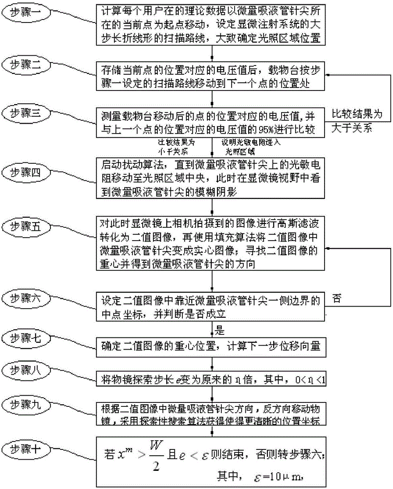
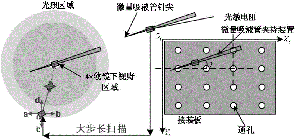
[0035] The large-scale automatic positioning method of the micropipette needle tip in the robot-assisted microinjection system of this embodiment, the large-scale refers to, compared with the existing needle tip positioning method when the initial position of the needle tip is a 4mm cube near the field of view , the allowable initial position range is expanded to 114mm×75mm×4mm, 114mm×75mm×4mm specifically means that the moving range of the stage on the horizontal plane is 114mm long and 75mm wide, and the moving range of the microscope objective lens in the vertical direction is 4mm . combine figure 1 As shown, the method is realized through the following steps: after the photoresistor is installed on the micropipette and the camera is installed on the microscope,
[0036] Step 1. Move the tip of the micropipette from the right side of the microscope field of view to the illuminated area, and move from the current point where the tip of the micropipette is located as the sta...
specific Embodiment approach 2
[0054] The difference from the specific embodiment 1 is that, in the large-scale automatic positioning method of the micropipette needle tip in the robot-assisted microinjection system of the present embodiment, the process of the disturbance algorithm described in step 4 is as follows:
[0055] Step 41. Move the stage to the left, right, front, and back (the left, right, front, and back directions mentioned here are determined relative to the position of the current point in the field of view of the microscope) by a small amount. Distance to four points a, b, c, d, and measure the voltage value of each point;
[0056] Step 42, according to Calculate the estimated value of the voltage gradient at the current position; and define the intermediate variable s=diag{q,q}grad f(o(k)) ∞ -Δp,
[0057] If s≤0, then
[0058] If s>0, then o(k+1)=o(k)+diag{q,q}grad f(o(k)),
[0059] If the voltage values at the four points a, b, c, and d are all greater than the voltage measured ...
specific Embodiment approach 3
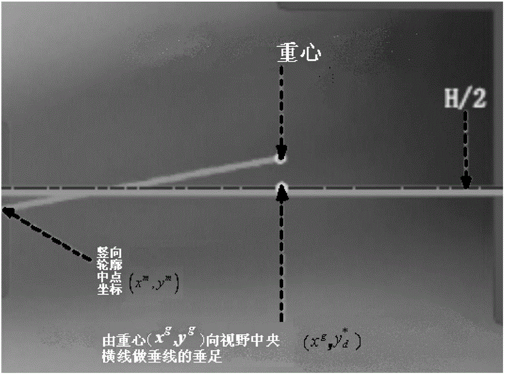
[0063] The difference from Embodiment 1 or Embodiment 2 is that the process of determining the center of gravity position of the image described in step 7 is as follows: Determine the coordinates of the center of gravity of the image (x g ,y g ), get the next step displacement vector mobile stage;
[0064] in, I(x,y) represents the pixel intensity at point (x,y); represents half the width of the field of view, t x and t y stands for displacement gain.
PUM
 Abstract
Description
Claims
Application Information
 - R&D Engineer
- R&D Manager
- IP Professional
- Industry Leading Data Capabilities
- Powerful AI technology
- Patent DNA Extraction
Browse by: Latest US Patents, China's latest patents, Technical Efficacy Thesaurus, Application Domain, Technology Topic, Popular Technical Reports.
© 2024 PatSnap. All rights reserved.Legal|Privacy policy|Modern Slavery Act Transparency Statement|Sitemap|About US| Contact US: help@patsnap.com


