


Quick Research
Generate reliable direction feasibility study reports for your R&D in just a few steps.

Technical Q&A
Discover and master advanced knowledge NOW. Basics, ideas, possibilities, all at once.

Find Solutions
As an expert in R&D theories, this can generate solutions to your technical problems instantly.

Evaluate Feasibility
Analyze your overall solution with one click, know your potential R&D risks in advance.

Monitor Landscape
Get weekly tech updates, stay abreast of the latest tech innovations and key insights.
Device for machining multiple surfaces of part
A part and end face technology, which is used in the field of devices for machining multiple surfaces of parts, can solve the problems of no angle head milling cutter, inability to process, and inaccessibility of the cutter body due to its large width.
- Summary
- Abstract
- Description
- Claims
- Application Information
AI Technical Summary
Problems solved by technology
Method used
Image


Examples
Embodiment 1
[0045] Embodiment 1: Combined cutter
[0046] exist Figure 4 Among them, one sleeve (105) on the upper side of the handle shaft and one sleeve (101) on the lower side of the handle shaft are matched to realize the sleeve (105) on the upper side of the handle shaft and the sleeve (101) on the lower side of the handle shaft. The inner hole of the handle shaft is coaxial, and the sleeve (105) on the upper side of the handle shaft has a T-shaped groove at the connection with the sleeve (101) on the lower side of the handle shaft. Tighten the nut (103), so that the upper sleeve of the handle shaft (105) and the lower sleeve of the handle shaft (101) are integrated, loosen the lock nut (103), and the upper sleeve of the handle shaft can be adjusted The relative angle between (105) and the underside sleeve (101) of the handle shaft. The outer worm gear support sleeve (102) is installed in the upper side sleeve (105) of the tool handle shaft and the lower side sleeve (101) of the t...
Embodiment 2
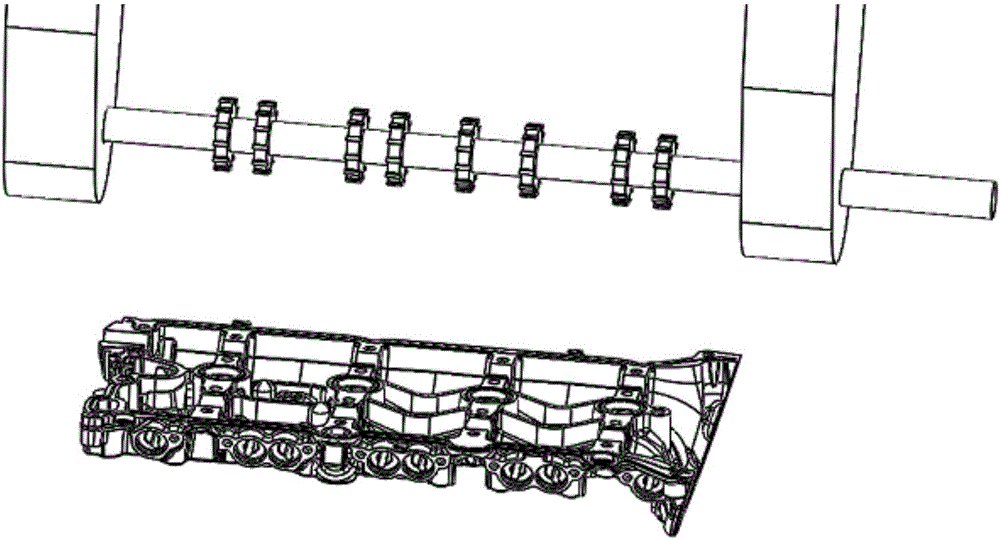
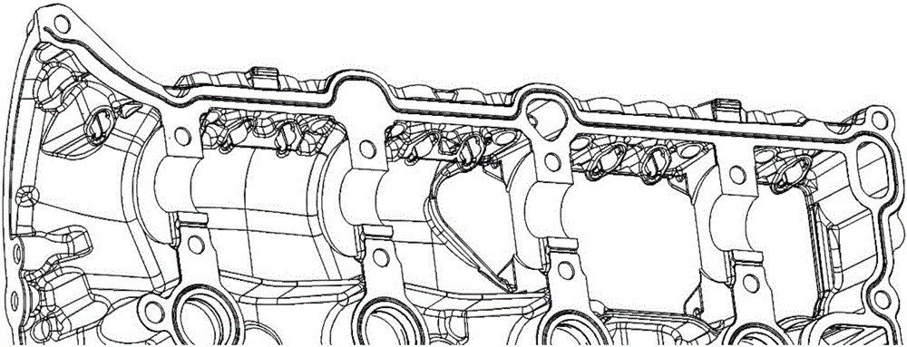
[0048] Embodiment 2: Fixture for parts
[0049] This embodiment utilizes the existing fourth-axis turntable fixture (211) of the machining center in the market to design a device for clamping and processing two workpieces at one time. Equipped with tailstock (204), the bottom is connected on the base plate (201), the height of the tailstock (204) is adjusted by the adjustment block (203), and the tailstock (204) passes the tailstock T-shaped positioning block (243) and the second The tension bolt (242) connects the tailstock L plate (205), the turntable L plate (210) passes through the turntable T-shaped positioning block (214) and the first tension bolt (209) and the turntable oil passage plate (250) and the turntable rotation The body (251) is connected and can rotate accordingly. The clamp body (206) is installed on the tailstock L plate (205) and the turntable L plate (210), and is fixed by the fastening bolt (245) and the positioning pin (244). Fixed, the clamp body (206...
Embodiment 3
[0051] Embodiment 3: Installation of a device for processing multiple surfaces of a part
[0052] Such as Figure 11 , 12 : 301, fixture, 302, hollowing opening of the fixture, 303, machine tool spindle, 304, angle head milling cutter positioning block, 305, angle head milling cutter, 306, milling cutter disc, 307, first oil pipe joint, 308, compressed air Air inlet joint, 309, the second oil pipe joint, 310, the sixth pressure plate, 311, T-shaped groove, 312, the machine tool table.
[0053] In Embodiment 3, the fixture (306) is installed on the machine tool table (315) and fixed in the T-shaped groove (304) by the sixth pressing plate (303), the first oil pipe joint (310) and the second oil pipe joint ( 312) are respectively connected to two hydraulic oil ports of hydraulic oil, and the compressed air inlet joint (311) is connected to the compressed air port; the handle of the angle head milling cutter (308) is installed in the machine tool spindle (301), Locating pin is...
PUM
 Abstract
Description
Claims
Application Information
 - R&D Engineer
- R&D Manager
- IP Professional
- Industry Leading Data Capabilities
- Powerful AI technology
- Patent DNA Extraction
Browse by: Latest US Patents, China's latest patents, Technical Efficacy Thesaurus, Application Domain, Technology Topic, Popular Technical Reports.
© 2024 PatSnap. All rights reserved.Legal|Privacy policy|Modern Slavery Act Transparency Statement|Sitemap|About US| Contact US: help@patsnap.com