
Hotel security and protection system

A security system and hotel technology, applied in closed-circuit television systems, instruments, data processing applications, etc., can solve the problems of time-consuming and laborious, entrance and exit security control, energy-saving control, insufficient service system, negligence, etc., to achieve advanced technology, reliability, system Mature and Compatible Effects

Inactive Publication Date: 2017-02-01
裴秀琴
View PDF4 Cites 0 Cited by
  • Summary
  • Abstract
  • Description
  • Claims
  • Application Information

AI Technical Summary

Problems solved by technology

[0002] With the continuous improvement of material life, people have higher requirements for the daily living environment, and general hotels do not do enough in terms of entrance and exit safety control, energy-saving control, service system, etc.
In terms of entrance and exit security, if you want to detect whether there are dynamic objects in the surrounding environment, such as people entering prohibited areas, you must use multiple video cameras plus closed-circuit television, and have special personnel to watch the monitoring screen for a long time. Currently, for dynamic objects 1. Personnel intrusion monitoring technology, now generally use cameras and closed-circuit television systems for personnel monitoring; this technology requires a special person to watch the screen, which is time-consuming and laborious. After a long time, the monitoring personnel are prone to fatigue and negligence
Existing hotels lack a security system that can dynamically monitor and supervise the public areas on all floors of the hotel to prevent non-registered personnel from entering the room and can be managed centrally

Method used


Image

  • Hotel security and protection system

Examples


Embodiment Construction

[0018] The principles and features of the present invention are described below in conjunction with the accompanying drawings, and the examples given are only used to explain the present invention, and are not intended to limit the scope of the present invention.

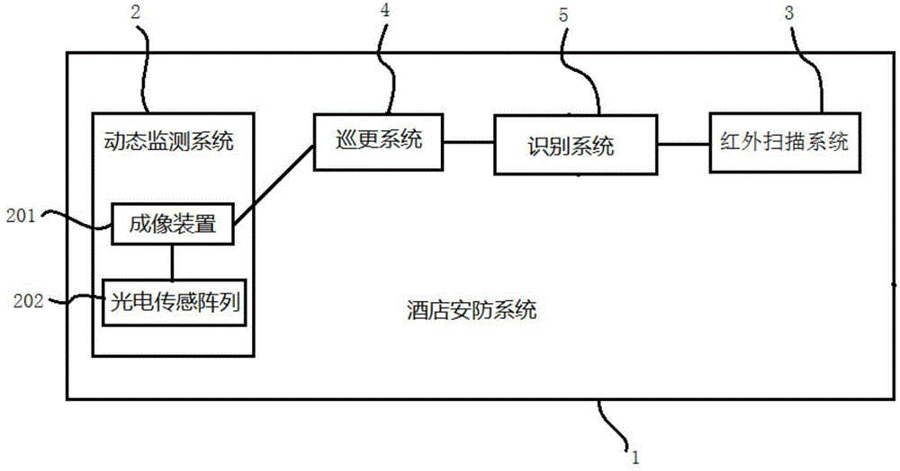
[0019] like figure 1 A hotel security system shown includes a dynamic monitoring system 2, an infrared scanning system 3, a patrol system 4 and an identification system 5;

[0020] The dynamic monitoring system 2 is used to photograph the scene in the target area, and convert the photographed image information into photoelectric information to realize dynamic monitoring;

[0021] The infrared scanning system 3 is used to scan and record the number of people entering and leaving the room;

[0022] The identification system 5 is connected with the infrared scanning system 3 and used to display the number of people entering and leaving the room;

[0023] The patrol system 4 is respectively connected with the dynamic ...


PUM


Abstract

The invention relates to a hotel security and protection system, comprising a dynamic monitoring system, an infrared scanning system, a patrol system and an identification system. The dynamic monitoring system is used for photographing a scene in a target area and carrying out photoelectric information conversion on the photographed image information, thereby realizing dynamic monitoring; the infrared scanning system is used for carrying out mutual identification with a wristband and scanning to record the number of people walking in and out of rooms; the identification system is connected with the infrared scanning system and is used for displaying the number of people walking in and out of the rooms; the patrol system is connected with the dynamic monitoring system and is used for carrying out wireless sensing patrol on the specific target area; and the wristband is used for recording room information and carrying out mutual identification with the infrared scanning system. The system is a complete and independent system. The security and thoroughness are realized and consideration is given to all things according to strict, reasonable, reliable, economical and complete thoughts. The video monitoring system, the infrared scanning system and the patrol system are combined. The system is characterized by advanced and reliable technology and mature and compatible system.

Description

technical field [0001] The invention relates to the field of security technology, in particular to a hotel security system. Background technique [0002] With the continuous improvement of material life, people have higher requirements for the daily living environment, and general hotels do not do enough in terms of entrance and exit safety control, energy saving control, and service system. In terms of entrance and exit security, if you want to detect whether there are dynamic objects in the surrounding environment, such as people entering prohibited areas, you must use multiple video cameras plus closed-circuit television, and have special personnel to watch the monitoring screen for a long time. Currently, for dynamic objects 1. Personnel intrusion monitoring technology, now generally use cameras and closed-circuit television systems for personnel monitoring; this technology requires special personnel to watch the screen, which is time-consuming and laborious. After a lon...

Claims


Application Information

Patent Timeline
Patent Type & Authority Applications(China)
IPC IPC(8): H04N7/18G07C9/00G06Q50/12
CPCG06Q50/12G07C9/27H04N7/18
Inventor 裴秀琴
Owner 裴秀琴
Learn More