Printed alternating-current motor
A technology for AC motors and printed boards, applied in the direction of asynchronous induction motors, electrical components, electromechanical devices, etc., can solve the problems of not being able to make full use of the limited space of printed boards, not being able to estimate the position and speed of the rotor, and being unfavorable for motor control, etc. , to achieve the effect of facilitating large-scale production, saving manpower and material resources, and simplifying the printed circuit structure
- Summary
- Abstract
- Description
- Claims
- Application Information
AI Technical Summary
Benefits of technology
Problems solved by technology
Method used
Image
Examples
Embodiment 1
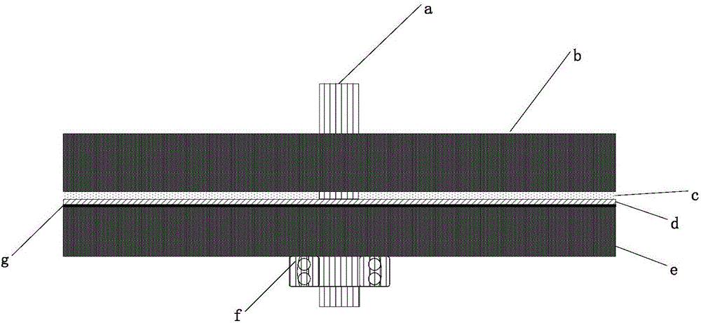
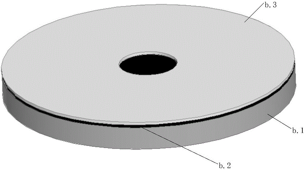
[0047] The printed asynchronous motor is composed of rotor core b1, rotor printed board b3, air gap c, stator printed board d, stator core e, bearing f, stator insulating paper g, rotor insulating paper b2, along the two shaft gears The rotating shaft a is sequentially composed of rotor core b1-rotor insulating paper b2-multi-layer rotor printed board b3-rotor b-air gap c-multi-layer stator printed board d-stator-stator insulating paper g-stator core e - The arrangement of the bearings f.
[0048] The multi-layer stator printed board d is fixed on the stator core e through the installation and positioning holes, and multiple radial conductors are evenly distributed on each layer of the printed board, and a via hole is set at both ends of each radial conductor, and all layers are the same The positional radial conductors are connected in parallel with copper pillars using via holes, and the three-phase windings share the parallel radial part. The number of layers of the stator...
Embodiment 2
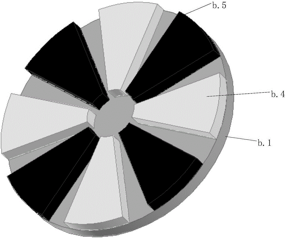
[0058] An embodiment of the present invention as a permanent magnet synchronous machine will be further described below in conjunction with the accompanying drawings: as figure 1 , image 3 , Figure 4 As shown, the printed permanent magnet synchronous motor is composed of two-shaft gear shaft a, rotor core b1, permanent magnet, air gap c, stator printed board d, stator core e, bearing f, and stator insulating paper g, along the The rotating shaft is arranged in sequence according to rotor core b1-permanent magnet-air gap c-multilayer printed board stator d-stator insulating paper g-stator core e-bearing.
[0059] The multi-layer stator printed board d is fixed on the stator core e through the installation and positioning holes, and multiple radial conductors are evenly distributed on each layer of the printed board, and a via hole is set at both ends of each radial conductor, and all layers are the same The positional radial conductors are connected in parallel with copper ...
PUM
 Abstract
Description
Claims
Application Information
 - R&D
- Intellectual Property
- Life Sciences
- Materials
- Tech Scout
- Unparalleled Data Quality
- Higher Quality Content
- 60% Fewer Hallucinations
Browse by: Latest US Patents, China's latest patents, Technical Efficacy Thesaurus, Application Domain, Technology Topic, Popular Technical Reports.
© 2025 PatSnap. All rights reserved.Legal|Privacy policy|Modern Slavery Act Transparency Statement|Sitemap|About US| Contact US: help@patsnap.com


