Small signal isolation transmission circuit

A transmission circuit and small signal technology, applied in signal transmission systems, electrical signal transmission systems, instruments, etc., can solve the problems of weak and small signals unable to transmit transmission errors, and achieve the goal of ensuring stability, improving output accuracy and prolonging service life. Effect

Inactive Publication Date: 2017-02-01
O&C ELECTRIC TECHN CO LTD
View PDF16 Cites 0 Cited by
  • Summary
  • Abstract
  • Description
  • Claims
  • Application Information

AI Technical Summary

Problems solved by technology

However, the existing circuits tend to be integrated, and the integration level is getting higher and higher, and the output analog signals are all weak small signals. However, due to the error of the HCNR201 optocoupler itself and its own transmission ratio, the weak and small signals cannot be detected. Larger transmission or transmission errors

Method used


Image

  • Small signal isolation transmission circuit

Examples


Embodiment Construction

[0024] The present invention will be further described in detail below in conjunction with the accompanying drawings and specific embodiments.

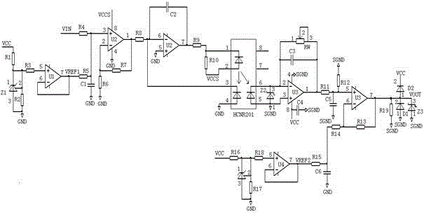
[0025] Such as figure 1 Shown: a small signal isolation transmission circuit, including a first reference circuit, a first reference circuit, an addition circuit, an isolation circuit, a proportional adjustment circuit, a subtraction circuit, and a limiter clamp circuit.

[0026] The first reference circuit includes a resistor R1, a resistor R2, a resistor R3, an operational amplifier U1, and a Zener diode Z1. The fifth pin of U1 is connected to the input terminal VCC through R3 and R1, and the sixth pin of U1 is connected to the seventh pin of U1. The first pin of Z1 is connected between R1 and R3, the second pin of Z1 is connected between R2 and R3, the third pin of Z1 and one end of R2 are grounded. Among them, Zener diode Z1 can be used as a high-precision reference voltage source, which can generate a high-precision voltage refe...


PUM


Abstract

A small signal isolation transmission circuit comprises a first reference circuit, a second reference circuit, a summing circuit, an isolation circuit, a proportional adjusting circuit, a subtraction circuit, and an amplitude limiting clamp circuit; the summing circuit comprises resistor R4, resistor R5, resistor R6, resistor R7, operational amplifier U2 and capacitor C1; the isolation circuit comprises resistor R8, resistor R9, resistor R10, operational amplifier U2, capacitor C2, and optocoupler HCNR201; the proportional adjusting circuit comprises voltage regulating diode Z2, operational amplifier U3, capacitor C3, capacitor C4, and potentiometer RW; the subtraction circuit comprises resistor R11, resistor R12, resistor R13, resistor R14, resistor R15, operational amplifier U3, capacitor C5, and capacitor C6. The small signal isolation transmission circuit has small transmission error and wild applicable transmission range.

Description

technical field [0001] The invention relates to an isolation circuit, in particular to a small signal isolation transmission circuit. Background technique [0002] The existing HCNR201 isolated signal transmission circuit, whose voltage is from the VIN terminal to the VOUT terminal, can output the required voltage signal through the HCNR201 isolated linear conversion of the primary side voltage signal, and send the signal to the minimum system such as CPU. The principle is that the input primary side voltage signal is isolated and output VOUT signal through HCNR201 analog optocoupler, and the primary side signal forms an automatic closed loop with the input VIN terminal through another feedback signal of the optocoupler, thereby outputting a stable voltage signal with a certain proportional relationship. However, the existing circuits tend to be integrated, and the integration level is getting higher and higher, and the output analog signals are all weak small signals. Howev...

Claims


Application Information

Patent Timeline
Patent Type & Authority Applications(China)
IPC IPC(8): G08C19/36
CPCG08C19/36
Inventor 孙志林王颖曜杨斌汤世娟
Owner O&C ELECTRIC TECHN CO LTD
Why Eureka
Try Eureka