Pipe jacking machine tool pipe and its application

A technology of tool pipe and pipe jacking machine, which is applied in the direction of pipes/pipe joints/fittings, mechanical equipment, pipeline laying and maintenance, etc. It can solve the problems of long construction period, increase the direct cost of the project, prolong the construction period, etc., and achieve good economic benefits and social benefits, easy to make and reuse, and simple construction methods

Active Publication Date: 2018-12-11
HUNAN CITY UNIV
View PDF6 Cites 0 Cited by
  • Summary
  • Abstract
  • Description
  • Claims
  • Application Information

AI Technical Summary

Problems solved by technology

For the former, the method of grouting is usually used to pre-reinforce the earthwork at the front end of the tool pipe, which increases the direct cost of the project and prolongs the construction period, and the grout for pre-reinforcement grouting is easy to wrap the tool pipe, which is easy to cause subsequent tool pipe tops Sharp increase in force and severe deformation of the tool tube
For the latter, the current method is a passive reinforcement method, usually after adding a temporary retaining structure, and then adopting the method of grouting to reinforce the front end of the tool pipe, the cost is higher than the former, and the construction period is longer than the former

Method used


Image

  • Pipe jacking machine tool pipe and its application
  • Pipe jacking machine tool pipe and its application
  • Pipe jacking machine tool pipe and its application

Examples


Embodiment 1

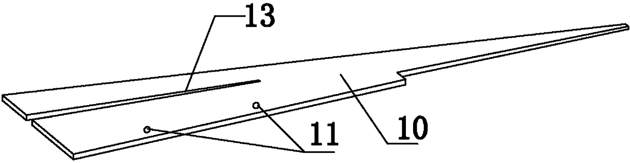
[0023] Depend on Figure 1 to Figure 6 It can be seen that a pipe jacking machine tool pipe comprises a pipe body 1, and the inner side of the front end of the pipe body 1 is provided with a compacting mechanism and a pushing mechanism of the compacting mechanism; 5. The compacting block 9 composed of the end plate 6, the first connecting side plate 10 and the second connecting side plate 8, and the mortise and tenon on the first connecting side plate 10 and the second connecting side plate 8 are formed between the compacting blocks 9 The mechanism is connected into a squeeze ring, and the squeeze ring can move axially in the tool tube; the propulsion mechanism includes a jack 19 and a bracket, the bracket is installed on the inside of the pipe body 1, the cylinder of the jack 19 is installed on the bracket, and the piston of the jack 19 It is in contact with the end plate 6 on the compacting block 9 .

[0024] The mortise and tenon mechanism of the present invention includes...

Embodiment 2

[0033] In order to install the earth retaining plate, the conical plate 5 of the present invention is provided with a limit plate 12, and a limit groove 15 is formed between the end plate 6 and the limit plate 12, and an earth retaining plate is installed in the limit groove 15; the earth retaining plate It includes a top earth retaining board 20 , a perforated earth retaining board 21 , a non-porous earth retaining board 22 and a bottom earth retaining board 23 .

[0034] For the convenience of installing the earth retaining plate, the earth retaining plate of the present invention is provided with a handle. Handles are all provided on the top floor earth retaining plate 20 , the perforated earth retaining plate 21 , the non-porous earth retaining plate 22 and the bottom earth retaining plate 23 .

[0035] In order to realize the grouting operation, the perforated soil retaining plate 21 of the present invention is provided with a grouting hole 24 .

[0036] An application o...

Embodiment 3

[0041] An application of the tool pipe of a pipe jacking machine as described above in pipe jacking construction, that is, when there is an obstacle in front of the pipe face or the soil with good self-stabilization performance, the jack 19 of the propulsion mechanism is depressurized, which can realize the Handling of obstructions or excavation of face openings.

[0042] When the present invention works, when an obstacle appears in front of the drill face or encounters a soil body with strong self-stabilization ability, the jack 19 releases the pressure, and the squeeze ring automatically retracts into the tube body 1 during the tool tube advancement process, which can Realize the treatment of obstacles or the opening excavation of the face.

[0043] The rest are the same as embodiment 1.


PUM


Abstract

The invention discloses a pipe jacking machine tool pipe which can be applied under different geological conditions. The pipe jacking machine tool pipe comprises a pipe body and is characterized in that a compaction mechanism and a pushing mechanism of the compaction mechanism are arranged on the inner side of the front end of the pipe body, the compaction mechanism comprises compaction blocks, each compaction block consists of circular-arc-shaped side plates, a conical plate, an end plate, a first connecting side plate and a second connecting side plate, the compaction blocks are connected through tenon-and-mortise mechanisms on the first connecting side plates and the second connecting side plates to form a compaction ring, and the compaction ring can axially move in the tool pipe. The pushing mechanism comprises a jack and a support, wherein the support is installed on the inner side of the pipe body, a cylinder body of the jack is installed on the support, and a piston of the jack is in contact with the end plates on the compaction blocks. In open large-caliber pipe jacking construction, the compaction mechanism can conduct compaction, reinforcing and seepage prevention on a front soil body of a water seepage stratum or a soft soil stratum or conduct rapid and effective plugging on an excavating face through a soil retaining plate, and the compaction mechanism can effectively retreat when encountering a stratum having strong self-stabilization capability or an obstacle. The construction method is simple, economical and environmentally friendly.

Description

technical field [0001] The invention relates to the field of underground engineering construction, in particular to a tool tube of a pipe jacking machine and its application, in particular to a tool tube of a pipe jacking machine capable of handling different geological conditions and its application. Background technique [0002] Pipe jacking construction is a non-excavation construction method, and it is a pipeline burying construction technology that does not excavate or excavates less. In the field of municipal and underground engineering construction, the application scope of pipe jacking method is more and more extensive. When using manual or semi-mechanical methods for long-distance large-diameter pipe jacking construction, soil layers with different self-stabilization capabilities may be encountered along the way. When encountering water-seepage strata and soft soil strata, the self-stabilization ability of the face is relatively poor. Water seepage and earthwork co...

Claims


Application Information

Patent Timeline
Patent Type & Authority Patents(China)
IPC IPC(8): F16L1/028F16L1/06
CPCF16L1/028F16L1/06
Inventor 黎永索曾旺辉张胜洪亮毛广湘
Owner HUNAN CITY UNIV
Why Eureka
Try Eureka