
Earthquake control system of high-speed railway bridge

A technology for earthquake damage and high-speed railways, applied in bridges, bridge parts, bridge construction, etc., can solve the problems that the stirrups are difficult to effectively restrain the core concrete, cannot meet the seismic requirements, and it is difficult to form plastic hinges, so as to reduce the residual deformation after the earthquake , increase the repairability after the earthquake, and reduce the effect of residual deformation

Active Publication Date: 2017-01-25
INST OF DISASTER PREVENTION
View PDF9 Cites 13 Cited by
  • Summary
  • Abstract
  • Description
  • Claims
  • Application Information

AI Technical Summary

Problems solved by technology

[0003] For the seismic problems of such major traffic projects, the traditional theory of bridge ductile seismic design can no longer meet its seismic requirements.
The main reasons are: (1) In order to meet the driving requirements of the high-speed railway, the lateral stiffness of the pier must be very large, which results in a large cross-section and a low ratio of longitudinal reinforcement, making it difficult for the stirrups to effectively restrain the core concrete and form a plastic hinge. And consume earthquake energy; (2) A large number of high-speed railway bridges span rivers, lakes and other harsh environments, are highly corrosive, and have outstanding durability problems. The cracking and damage of bridge piers after earthquakes must be strictly limited; (3) In order to ensure the high-speed railway track For the smooth operation of high-speed trains and the safety of high-speed trains, the post-earthquake residual deformation of bridge piers and girders must be strictly limited; (4) High-speed railways are major traffic projects. The post-earthquake inspection and repair of bridge damage and damage must be completed quickly, which requires strict control of bridge pier concrete cracking and other damage

Method used


Image

  • Earthquake control system of high-speed railway bridge
  • Earthquake control system of high-speed railway bridge
  • Earthquake control system of high-speed railway bridge

Examples


Embodiment Construction

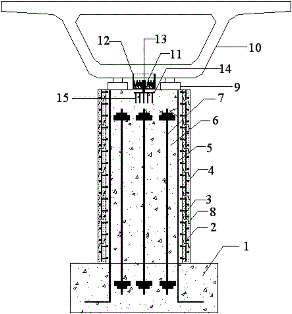
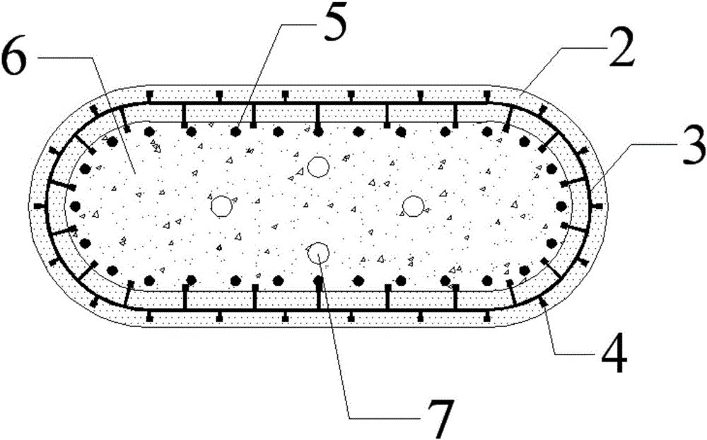
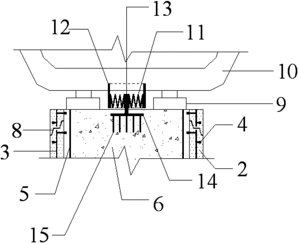
[0029] Such as Figure 1 to Figure 4 A high-speed railway bridge earthquake damage control system shown includes: including, pier foundation, prefabricated shell wall composed of ECC and steel plates. Longitudinal reinforcement is arranged inside the prefabricated shell wall and concrete is poured, and unbonded prestressed reinforcement is vertically arranged along the pier. Two movable supports are set on the top of the pier to connect with the main girder. And 4 SMA coil springs are set between the top of the pier and the main girder.

[0030] The prefabricated shell walls composed of ECC and steel plates are arranged in sections along the pier height and connected by joints. The joints are toothed, which is convenient for the occlusion of the upper and lower prefabricated shell walls.

[0031] The unbonded prestressed tendons pass through the pier vertically, the bottom is anchored in the foundation, and the top is anchored in the upper part of the pier.

[0032] Studs ...


PUM


Abstract

The invention discloses an earthquake control system of a high-speed railway bridge, comprising a prefabricating shell wall composed of high ductility cementitious composite (ECC)-steel plate to form a pier, wherein a vertical unbonded tendon is set in the pier. The top of the pier is connected with a main beam at the upper part by two movable supports; and a shape memory alloy (SMA) spiral spring is set between the top of the pier and the main beam. The SMA spiral spring is respectively connected with a steel sleeve and a square steel rod. The upper part of the steel sleeve is embedded into the bottom of the main beam; the lower part of the square steel rod is embedded into the top of the pier. The prefabricating shell wall becomes the template of inner concrete construction in the pier; the shearing strength and ductility energy consumption of the pier are provided; the crack damage under the earthquake can be reduced; and the residual displacement of the pier is reduced by the unbonded tendon. SMA spiral spring can provide the level rigidity under the normal operation as well as energy consumption under the earthquake and self-resetting ability of the main beam. The movable support can provide vertical rigidity and bearing capacity.

Description

technical field [0001] The invention relates to a bridge structure system in civil engineering, in particular to a high-speed railway bridge system using prefabricated shell walls and SMA coil springs. Background technique [0002] At present, the rapid development of my country's high-speed railway construction is bound to arouse people's great attention to the seismic safety of such major transportation projects. Bridge piers and main girders are the main load-bearing components of bridge structures, and the seismic safety of bridge piers and main girders is the guarantee for the seismic safety of high-speed railway bridges. [0003] For the seismic problems of such major traffic projects, the traditional theory of ductile seismic design of bridges can no longer meet the seismic requirements. The main reasons are: (1) In order to meet the driving requirements of the high-speed railway, the lateral stiffness of the bridge pier must be very large, which results in a large c...

Claims


Application Information

Patent Timeline
IPC IPC(8): E01D19/00E01D19/02
CPCE01D19/00E01D19/02Y02A30/30
Inventor 孙治国刘瑜丽何福
Owner INST OF DISASTER PREVENTION
Learn More