Locking device for rotating shaft of washing machine

A technology for locking devices and rotating shafts, which can be used in washing devices, other washing machines, textiles and papermaking, etc. It can solve the problems of difficult axial clearance control, non-detachable, difficult to control shrinkage ratio, etc., and achieves a good limit effect and easy loading Lightweight, cleverly designed effects

Active Publication Date: 2018-07-13
NINGGUO JULONG IND
View PDF8 Cites 0 Cited by
  • Summary
  • Abstract
  • Description
  • Claims
  • Application Information

AI Technical Summary

Problems solved by technology

[0002] The rotating shaft of the existing pulsator type washing machine has a washing shaft and a dehydration shaft. The upper part is mainly blocked by pressing the convex step on the inner convex step of the dehydration shaft, and then the other end of the washing shaft passing through the dehydration shaft is clamped with a circlip. This assembly method is axially locked by the circlip , the washing shaft is not easy to pull out from the dehydration shaft, which is safe, but the washing shaft must be processed with a specific groove for installing the circlip, which increases the processing process. When assembling, it must be installed with a special circlip pliers. The thickness of the copper gasket is adjusted, and the follow-up assembly method of related parts is single and cannot be disassembled. When there is a bad situation, it can only be reworked by destroying it. Not only is it troublesome, but it is also very uneconomical.
[0003] Some use the locking device of the positioning sleeve. This assembly method is convenient for assembly, but it is difficult to control the axial clearance. Because the positioning sleeve is often processed by plastic through the mold, the shrinkage ratio is difficult to control when the mold is processed, resulting in the outer diameter of the positioning sleeve. The concentric flatness is difficult to meet the requirements, and the washing shaft is installed in the dehydration shaft, which is easy to pull out, that is, the pull-off force is difficult to meet the requirements

Method used


Image

  • Locking device for rotating shaft of washing machine
  • Locking device for rotating shaft of washing machine
  • Locking device for rotating shaft of washing machine

Examples


Embodiment Construction

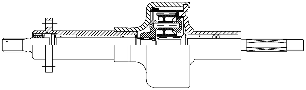
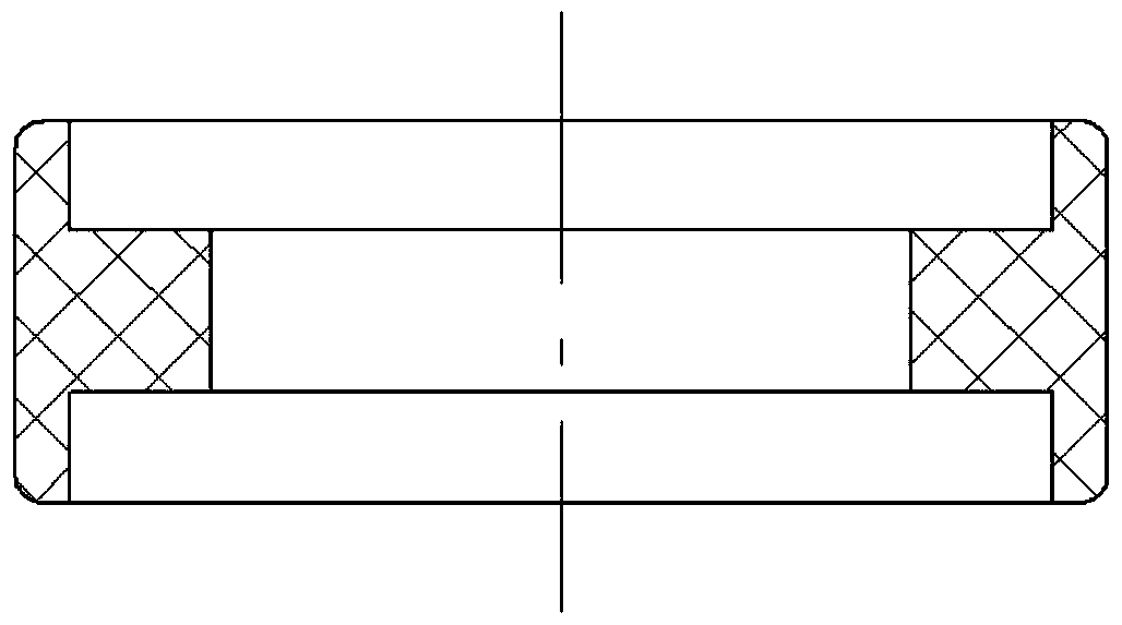
[0024] combine Figure 5-7 , is a schematic diagram of the principle structure of an embodiment of the locking device for the rotating shaft of a washing machine according to the present invention, which includes a body 1, which is provided with protruding teeth 2 that are evenly distributed outwards, and the connection between the protruding teeth 2 and the body is provided There is a circle of grooves 3 .

[0025] More specifically, the convex tooth 2 is square; the edge 4 of the outer end of the convex tooth 2 is set on a circle concentric with the center; the corners of the convex tooth 2 are rounded; The width of the protruding teeth 2 is less than or equal to the distance between adjacent protruding teeth 2; the locking device is molded from a metal material through punching and then integrally heat-treated.

[0026] Preferably, the hardness of the locking device after heat treatment is HRC47-53.

[0027] The locking device for the rotating shaft of the washing machine...


PUM


Abstract

The invention discloses a locking device of washing machine rotation axis, and relates to the technical field of speed reduction clutch of a washing machine. The locking device overcomes the insufficiencies of clamp-ring type locking device in complicated assembly, diseconomy, and uncontrollability of axial clearance. The locking device comprises a body portion, and is characterized by that double wedges are arranged outwards on the body portion in an equally distributed mode, a round of grooves are arranged on the joint of the double wedges and the body portion; the double wedges are in square shape, and the edge of the outer portion of the double wedges are all arranged on a circumference which shares one center with the double wedges; the corner portions of the double edges are provided with circular angles, and the breadths of the double wedges should be smaller or equal to the distance between every two adjacent double edges. The locking device of washing machine rotation axis is ingenious in design, easy to carry; meanwhile the locking device of washing machine rotation axis has larger pulling strength and better spacing effect. The locking device of washing machine rotation axis has the advantages of being light in quality, low in cost and convenient for production.

Description

technical field [0001] The invention relates to the technical field of a washing machine deceleration clutch, in particular to a locking device for a rotating shaft of a washing machine deceleration clutch. Background technique [0002] The rotating shaft of the existing pulsator type washing machine has a washing shaft and a dehydration shaft. The upper part is mainly blocked by pressing the convex step on the inner convex step of the dehydration shaft, and then the other end of the washing shaft passing through the dehydration shaft is clamped with a circlip. This assembly method is axially locked by the circlip , the washing shaft is not easy to pull out from the dehydration shaft, which is safe, but the washing shaft must be processed with a specific groove for installing the circlip, which increases the processing process. When assembling, it must be installed with a special circlip pliers. The thickness of the copper gasket is adjusted, and the follow-up assembly meth...

Claims


Application Information

Patent Timeline
Patent Type & Authority Patents(China)
IPC IPC(8): D06F37/30
CPCD06F37/30
Inventor 刘军江平国
Owner NINGGUO JULONG IND
Why Eureka
Try Eureka