underwater propeller propulsion

A technology of propulsion device and propeller, which is applied in the direction of propulsion transmission device, transmission device using synchronous propulsion components, ship propulsion, etc. Wear and tear and other problems, to achieve the effect of reducing the overall length, saving internal space, and overall compactness

Inactive Publication Date: 2018-01-05
张瑭
View PDF5 Cites 0 Cited by
  • Summary
  • Abstract
  • Description
  • Claims
  • Application Information

AI Technical Summary

Problems solved by technology

At present, the bearing design of existing underwater propeller propellers often adopts single bearing support. When such support rotates at high speed, the rotating shaft is easy to run out radially, which will cause excessive wear of the dynamic seal. The stability of the shaft has been improved, and its rotating shaft can only bear a large thrust in a single axial direction. If the propeller is reversed, the ability of its bearing group to withstand reverse thrust will be greatly reduced
In addition, many propellers currently on the market also have many defects in terms of sealing design and thrust-to-mass ratio, which cannot meet the requirements of underwater equipment for underwater high-performance propellers

Method used


Image

  • underwater propeller propulsion
  • underwater propeller propulsion

Examples


Embodiment Construction

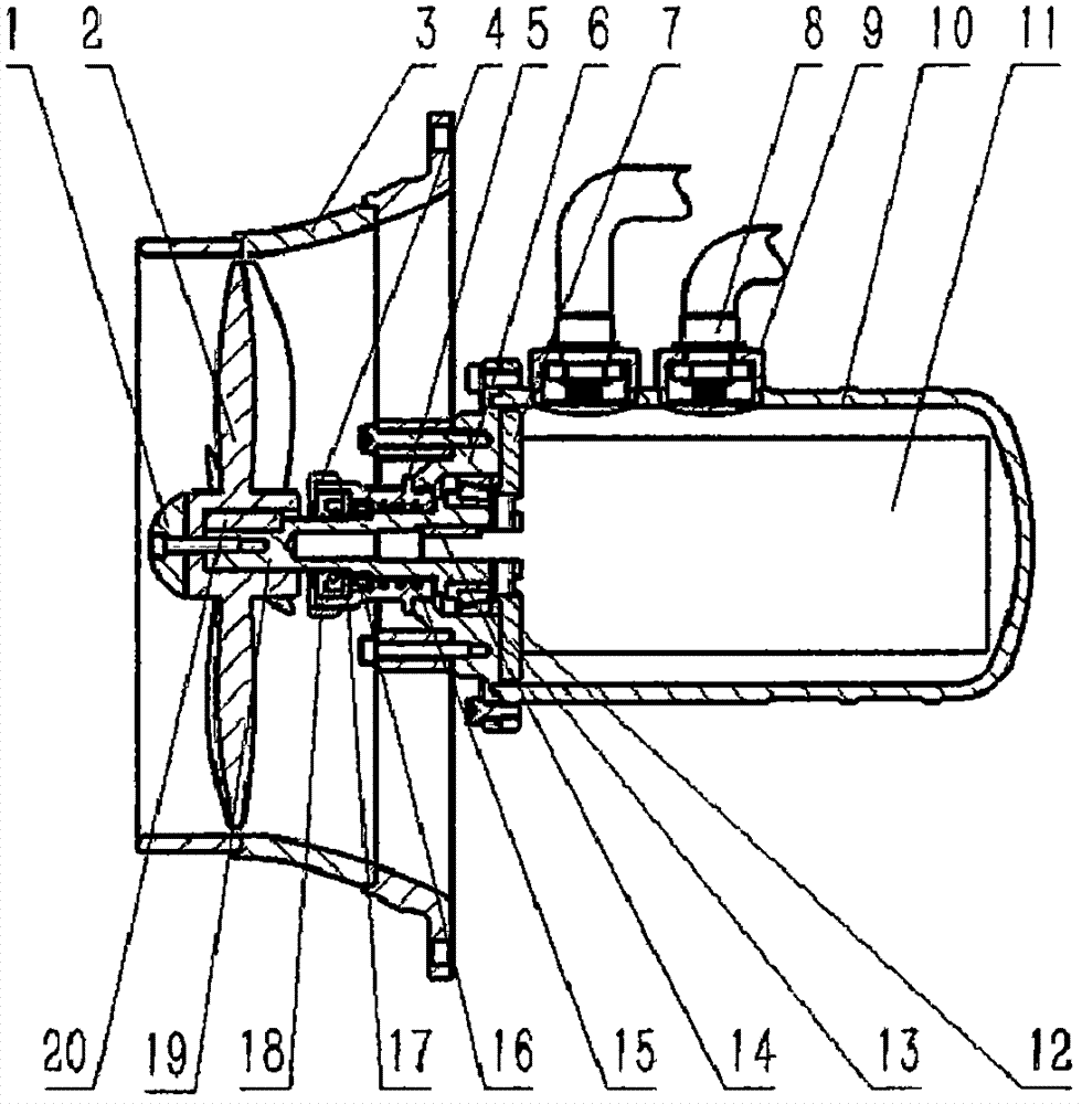
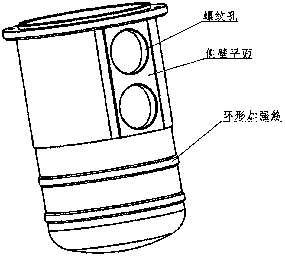
[0017] Various exemplary embodiments, features, and aspects of the invention will be described in detail below with reference to the accompanying drawings. The same reference numbers in the figures indicate functionally identical or similar elements. While various aspects of the embodiments are shown in the drawings, the drawings are not necessarily drawn to scale unless otherwise indicated.

[0018] The word "exemplary" is used exclusively herein to mean "serving as an example, embodiment, or illustration." Any embodiment described herein as "exemplary" is not necessarily to be construed as preferred or advantageous over other embodiments.

[0019] In addition, in order to better illustrate the present invention, numerous specific details are given in the specific embodiments below. It will be understood by those skilled in the art that the present invention may be practiced without certain specific details. In some instances, methods, means, components and circuits well k...


PUM


Abstract

The invention relates to an underwater propeller propelling device which comprises a driving motor, a propeller, a motor adapter part, an end cover, a driving device and a sealing device. The driving device comprises a rotating shaft, a first bearing, a second bearing and a driving auxiliary structure. The driving auxiliary structure comprises a bearing washer A and a bearing washer B. The rotating shaft is provided with shaft shoulders, and the second bearing and the first bearing are axially clamped on the rotating shaft through the shaft shoulders. The end where the output shaft of the driving motor is fixed to the motor adapter part, the motor adapter part is fixed to the end cover, the bearing washer A is arranged between the motor adapter part and the first bearing, and the first bearing and the end non-adjacent to the bearing washer A are axially clamped in the end cover through the first shaft shoulder of the rotating shaft. One end of the second bearing is pressed by the bearing washer B through a fixing device, and the other end of the second bearing is clamped on the second shaft shoulder of the rotating shaft. The sealing device is arranged between the first bearing and the second bearing, and the first bearing and the second bearing are arranged to respectively provide axially adverse axial restraining forces for the rotating shaft.

Description

technical field [0001] The invention relates to the field of electromechanical integration, in particular to an underwater propeller propulsion device. Background technique [0002] The underwater propeller propeller is the main device for the movement of underwater vehicles or robots, and its function is to provide navigation thrust or control attitude. At present, the bearing design of existing underwater propeller propellers often adopts single bearing support. When such support rotates at high speed, the rotating shaft is easy to run out radially, which will cause excessive wear of the dynamic seal. The stability of the shaft has been improved, and its rotating shaft can only bear a large thrust in a single axial direction. If the propeller is reversed, the ability of the bearing group to withstand the reverse thrust will be greatly reduced. In addition, many propellers currently on the market have many defects in terms of sealing design and thrust-to-mass ratio, which ...

Claims


Application Information

Patent Timeline
Patent Type & Authority Patents(China)
IPC IPC(8): B63H23/04B63H23/06B63H23/32
CPCB63H23/04B63H23/06B63H23/321B63H2023/327
Inventor 张瑭张建华李明雷
Owner 张瑭
Why Eureka
Try Eureka