
Battery

A battery pack, battery side technology, applied in the direction of batteries, battery pack components, secondary batteries, etc.

Active Publication Date: 2020-06-19
MAKITA CORP
View PDF3 Cites 0 Cited by
  • Summary
  • Abstract
  • Description
  • Claims
  • Application Information

AI Technical Summary

Problems solved by technology

Therefore, if the width of the pair of elastic clamping pieces in the direction perpendicular to the sliding direction is further enlarged, the size of the battery pack itself will increase.

Method used


Image

  • Battery
  • Battery
  • Battery

Examples


Embodiment Construction

[0029] In the battery pack according to some embodiments, an insertion guide portion is formed at an end portion of the pair of elastic holding pieces on a side that receives the device-side terminal. The insertion guide portion may be an insertion guide rib extending from ends of the pair of elastic clamping pieces. Alternatively, the insertion guide portion may be an insertion guide recess formed by cutting the ends of the pair of elastic holding pieces.

[0030] According to the battery pack described above, when the battery pack is mounted on a device, the device-side terminal can be smoothly inserted into the pair of elastic clamping pieces.

[0031] In the battery pack according to some embodiments, a pull-out guide portion is formed at an end portion of the pair of elastic holding pieces on a side opposite to a side receiving the device-side terminal. The pull-out guide portion may be a pull-out guide rib extending from ends of the pair of elastic clamping pieces.

[...


PUM


Abstract

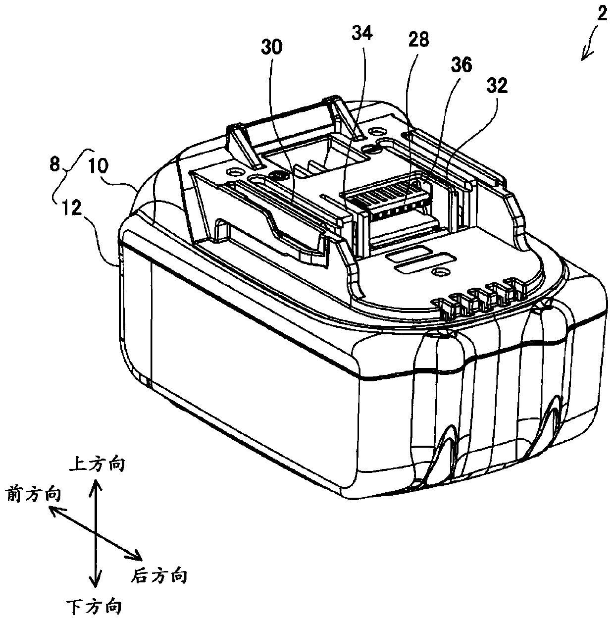
The present invention provides a battery pack capable of increasing the contact area between a device side terminal and a battery side terminal without increasing the size of the battery pack. This specification discloses a battery pack that can be attached to and detached from a device having a flat device-side terminal by sliding in a sliding direction along the device-side terminal. The battery pack includes a battery-side terminal that engages with the device-side terminal to be electrically connected. The battery-side terminal includes a pair of elastic clamping pieces configured to receive the device-side terminal and clamp the device-side terminal from both sides when the battery pack is mounted on the device. In the aforementioned battery pack, the pair of elastic clamping pieces extends in a direction perpendicular to the sliding direction.

Description

technical field [0001] The technology disclosed by this specification relates to a battery pack. Background technique [0002] Patent Document 1 discloses a battery pack that can be attached and detached by sliding relative to a device having flat device-side terminals in a sliding direction along the device-side terminals. The battery pack includes a battery-side terminal that engages with the device-side terminal to be electrically connected. The battery-side terminal includes an elastic holding piece configured to receive the device-side terminal and hold the device-side terminal from both sides when the battery pack is mounted on the device. In the above battery pack, the pair of elastic clamping pieces extend along the sliding direction. [0003] Patent Document 1: Japanese Patent Laid-Open No. 2013-191288 [0004] In order to suppress mechanical wear and electrical wear of the device-side terminal and the battery-side terminal, it is preferable to increase the conta...

Claims


Application Information

Patent Timeline
Patent Type & Authority Patents(China)
IPC IPC(8): H01M2/20H01M2/30H01M2/10H01M50/213H01M50/244H01M50/296H01M50/503H01M50/509H01M50/522H01M50/548H01M50/559
CPCH01M2220/20H01M50/503H01M50/548H01M50/296H01M50/244H01M50/213H01M50/559H01M50/522H01M50/509H01R4/4823H01M2220/30H01R13/113H01M10/6235Y02E60/10H01M10/0525H01R33/765
Inventor 内藤晃
Owner MAKITA CORP
Learn More