
Automatic pumping method for collecting well and pumping system based on automatic pumping method

A water well, automatic technology, applied in the direction of machine/engine, liquid variable capacity machinery, pump control, etc., can solve the problems of continuous operation of the water pump, prone to frequent failures, reducing the starting frequency and working time of a single water pump, etc. To achieve the effect of reducing the starting frequency and working time, and reducing the frequency of failures

Active Publication Date: 2017-01-18
DAZHOU POWER BUREAU SICHUAN ELECTRIC POWER +1
View PDF7 Cites 5 Cited by
  • Summary
  • Abstract
  • Description
  • Claims
  • Application Information

AI Technical Summary

Problems solved by technology

[0003] The purpose of the present invention is to provide an automatic water pumping method for water wells and a pumping device based on the method, so as to solve the problem of continuous operation and frequent failure of water pumps in small and medium-sized power stations in the prior art, and to reduce the start-up of a single water pump Frequency and working time, in order to reduce the frequency of water pump failure

Method used


Image

  • Automatic pumping method for collecting well and pumping system based on automatic pumping method
  • Automatic pumping method for collecting well and pumping system based on automatic pumping method
  • Automatic pumping method for collecting well and pumping system based on automatic pumping method

Examples


Embodiment 1

[0028] Such as Figure 4 The automatic water pumping method for the accumulated water well comprises the following steps:

[0029] (a) Preset the first water level, the second water level, and the third water level in order from low to high in the accumulated water well; the first water level is located within 1 / 3 of the depth of the accumulated water well, the second water level, the third water level The heights of the three water levels are all within 1 / 3 of the depth of the accumulated water well; at the same time, two water pumps capable of drawing water from the accumulated water well are configured, and the two water pumps are the first water pump and the second water pump; (b) keep the two water pumps at Initial closed state; (c) When the water level in the accumulated water well rises to the second water level, start the first water pump to pump water; when the water level in the accumulated water well drops to the first water level, turn off the first water pump; (d)...

Embodiment 2

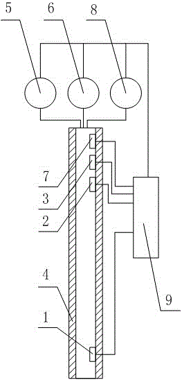
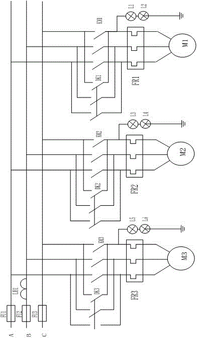
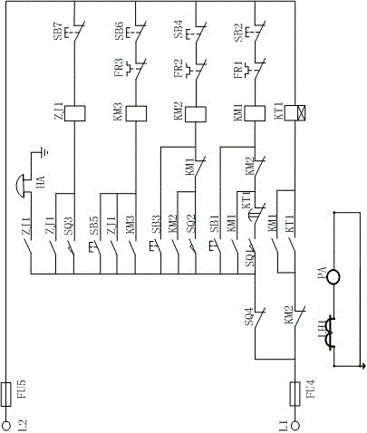
[0031] Such as Figure 1 to Figure 3 The shown automatic water pumping system for the accumulated water well includes a first water pump 5 and a second water pump 6 capable of pumping water from the accumulated water well; it also includes a water level control rod 4 suspended in the accumulated water well, and the water level control rod 4 has two ends Open pipe body structure, the first liquid level sensing device 1, the second liquid level sensing device 2, and the third liquid level sensing device 3 are arranged in the water level control rod 4 in sequence from low to high, wherein the first liquid level sensing device The level sensing device 1 is located in the lower 1 / 3 of the height of the accumulated water well, and the second liquid level sensing device 2 and the third liquid level sensing device 3 are located in the upper 1 / 3 of the height of the accumulated water well; The control rod 4 is a pipe structure with both ends open, and the signals of the first liquid le...


PUM


Abstract

The invention discloses an automatic pumping method for a collecting well and a pumping system based on the automatic pumping method. Different water level heights are set in the collecting well, the changes of water volumes between the different water level heights are matched with a first water pump and a second water pump, and the first water pump and the second water pump are used alternately to solve the problem that in the prior art, a collecting well water pump of a medium and small power plant works continuously and is prone to having failures frequently; and the purpose that the starting frequency and the working time of the single water pump are reduced to reduce the failure frequency of the water pump is achieved.

Description

technical field [0001] The invention relates to the field of drainage of accumulated water wells, in particular to an automatic pumping method for accumulated water wells and a pumping device based on the method. Background technique [0002] There are many small hydropower stations built on the tributaries of large rivers in areas with abundant water. Due to the long construction time, outdated equipment, large water leakage of unit cooling water and turbines, and relatively small water accumulation wells, these small hydropower stations require frequent work of pumping equipment. , leading to frequent failures of pumping equipment. Once the pumping equipment breaks down, the well will easily overflow with water, requiring manpower to continuously inspect and repair, causing a lot of tedious work for the workers and bringing a lot of inconvenience. Contents of the invention [0003] The purpose of the present invention is to provide an automatic water pumping method for ...

Claims


Application Information

Patent Timeline
Patent Type & Authority Applications(China)
IPC IPC(8): F04B49/06
CPCF04B49/06
Inventor 刘利德李波
Owner DAZHOU POWER BUREAU SICHUAN ELECTRIC POWER
Learn More