


Quick Research
Generate reliable direction feasibility study reports for your R&D in just a few steps.

Technical Q&A
Discover and master advanced knowledge NOW. Basics, ideas, possibilities, all at once.

Find Solutions
As an expert in R&D theories, this can generate solutions to your technical problems instantly.

Evaluate Feasibility
Analyze your overall solution with one click, know your potential R&D risks in advance.

Monitor Landscape
Get weekly tech updates, stay abreast of the latest tech innovations and key insights.
A method and device for detecting the rotor position of a permanent magnet synchronous motor
A permanent magnet synchronous motor, rotor position technology, applied in the estimation/correction of motor parameters, electronic commutator, motor control and other directions, can solve problems such as the failure of the Hall position sensor rotor position detection
- Summary
- Abstract
- Description
- Claims
- Application Information
AI Technical Summary
Problems solved by technology
Method used
Image

Examples
Embodiment 1
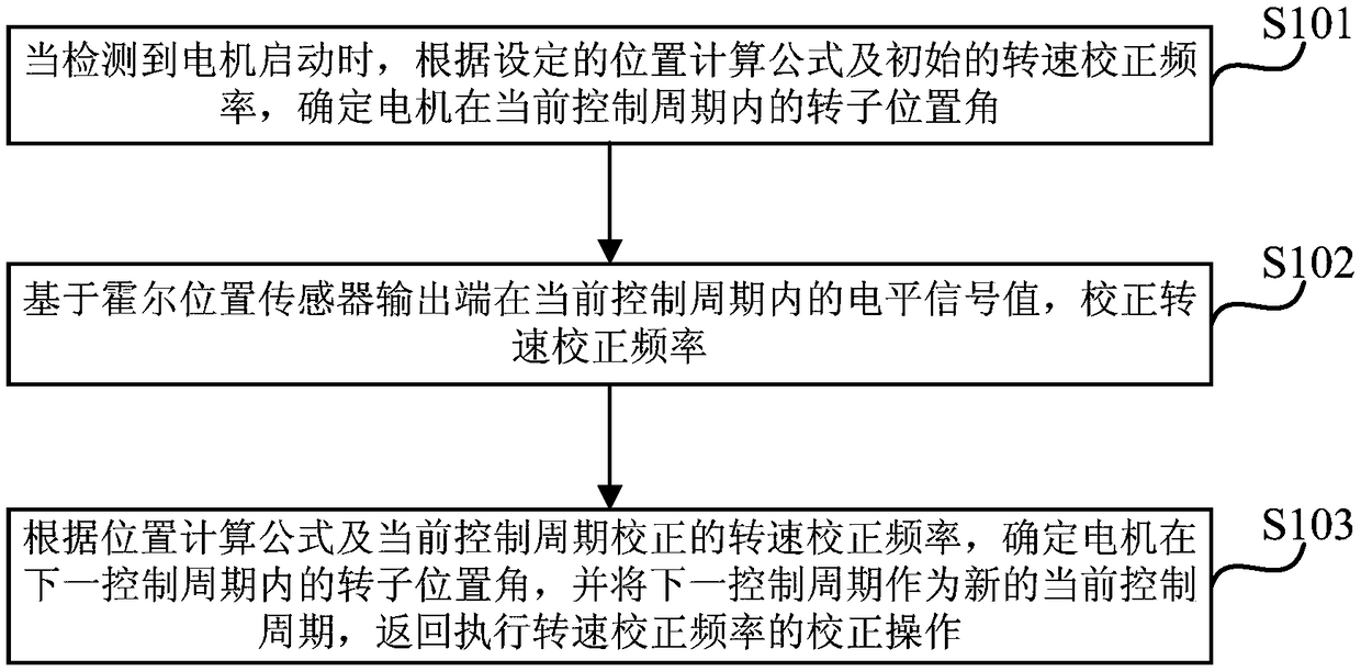
[0019] figure 1 A flow diagram of a method for detecting the rotor position of a permanent magnet synchronous motor provided in Embodiment 1 of the present invention. This method is suitable for real-time detection of the rotor position of a permanent magnet synchronous motor. The detection device is implemented, wherein the detection device can be implemented by software and / or hardware, and is generally integrated on a single-chip microcomputer used in conjunction with a permanent magnet synchronous motor.
[0020] Such as figure 1 As shown, the method for detecting the rotor position of a permanent magnet synchronous motor provided by Embodiment 1 of the present invention includes the following operations:
[0021] S101. When it is detected that the motor starts, according to the set position calculation formula and the initial speed correction frequency, determine the rotor position angle of the motor in the current control cycle.
[0022] In this embodiment, the control...
Embodiment 2
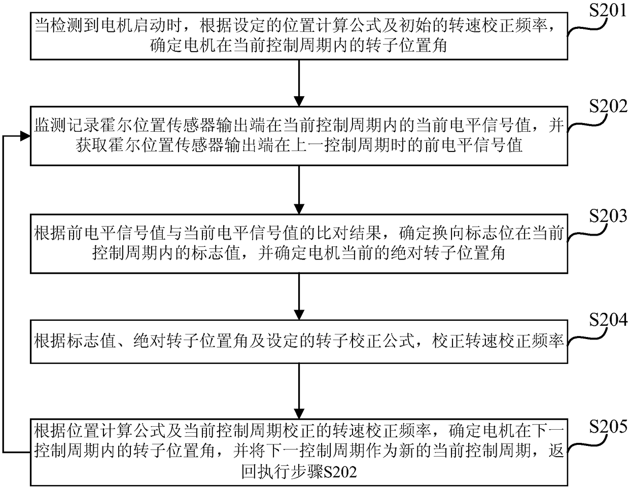
[0035] figure 2 It is a schematic flowchart of a method for detecting the rotor position of a permanent magnet synchronous motor provided in Embodiment 2 of the present invention. Embodiment 2 of the present invention is optimized on the basis of the above-mentioned embodiments. In this embodiment, "correct the rotational speed correction frequency based on the level signal value of the Hall position sensor output terminal in the current control cycle" is further Specifically: monitor and record the current level signal value of the output terminal of the Hall position sensor in the current control cycle, and obtain the previous level signal value of the output terminal of the Hall position sensor in the previous control cycle; according to The comparison result of the previous level signal value and the current level signal value determines the flag value of the commutation flag in the current control cycle, and determines the current absolute rotor position angle of the mot...
Embodiment 3
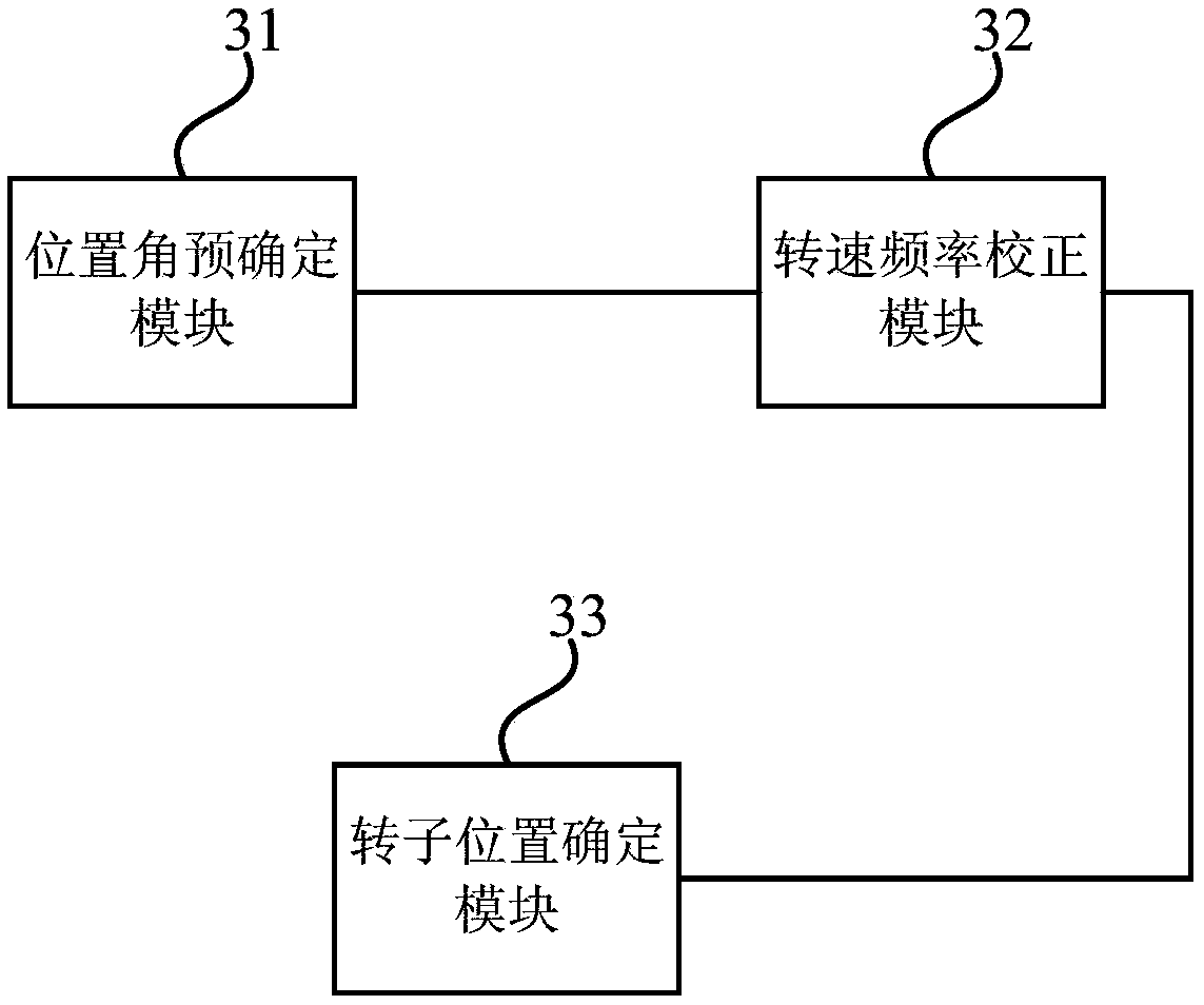
[0059] image 3 It is a structural block diagram of a detection device for the rotor position of a permanent magnet synchronous motor provided in Embodiment 3 of the present invention. The device is suitable for real-time detection of the rotor position of the permanent magnet synchronous motor, wherein the detection device can be realized by software and / or hardware, and is generally integrated on a single-chip computer used in conjunction with the permanent magnet synchronous motor. Such as image 3 As shown, the detection device includes: a position angle predetermined module 31 , a rotational speed frequency correction module 32 and a rotor position determination module 33 .
[0060] Wherein, the position angle pre-determining module 31 is used to determine the rotor position angle of the motor in the current control cycle according to the set position calculation formula and the initial speed correction frequency when the motor is detected to start.
[0061] The rotatio...
PUM
 Abstract
Description
Claims
Application Information
 - R&D Engineer
- R&D Manager
- IP Professional
- Industry Leading Data Capabilities
- Powerful AI technology
- Patent DNA Extraction
Browse by: Latest US Patents, China's latest patents, Technical Efficacy Thesaurus, Application Domain, Technology Topic, Popular Technical Reports.
© 2024 PatSnap. All rights reserved.Legal|Privacy policy|Modern Slavery Act Transparency Statement|Sitemap|About US| Contact US: help@patsnap.com