
A bridge switch device for power supply

A switching device and bridge-type technology, which is applied to the output power conversion device, electrical components, and the conversion of AC power input to DC power output, etc., can solve the problems of high cost, complicated circuit, troublesome separation of positive and negative electrodes, etc. The effect of long service life, simple principle and convenient implementation

Active Publication Date: 2019-05-28
濮阳市立圆汽车电器有限公司
View PDF10 Cites 0 Cited by
  • Summary
  • Abstract
  • Description
  • Claims
  • Application Information

AI Technical Summary

Problems solved by technology

The circuits involved in the above methods are complex and costly; and it is troublesome to separate the positive and negative poles when the load is connected to the power supply.

Method used


Image

  • A bridge switch device for power supply
  • A bridge switch device for power supply
  • A bridge switch device for power supply

Examples


Embodiment Construction

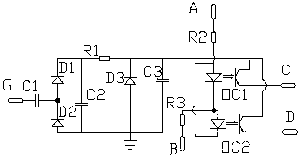
[0034] Such as figure 1 , figure 2 with image 3 The shown bridge switching device for power supply includes a housing 1 on which a positive input terminal 2 , a negative input terminal 3 , a first load terminal 4 , a second load terminal 5 and an AC terminal 6 are arranged. Among them, the positive input terminal 2 is used to connect the positive pole of the power supply, the negative input terminal 3 is connected to the negative pole of the power supply, the first load terminal 4 and the second load terminal 5 are respectively connected to the positive and negative poles of the load, and the AC terminal 6 is connected to the AC power supply.

[0035] A positive input pin E, a negative input pin F, a first load pin A, a second load pin B, a first control pin C, a second control pin D, and a first control circuit are set inside the housing 1 , the second control circuit, the third control circuit and the fourth control circuit. In order to ensure the stable operation of th...


PUM


Abstract

Disclosed is a bridge type switching apparatus for a power supply. A shell is provided with a positive electrode input terminal, a negative electrode input terminal, a first load terminal and a second load terminal, wherein a first control circuit, a second control circuit, a third control circuit and a fourth control circuit with the same structure are arranged in the shell; each of the first control circuit, the second control circuit, the third control circuit and the fourth control circuit comprises a PNP triode and an N-channel field effect transistor separately; and switch-on or cut-off of different control circuits is realized through connection between the PNP triodes and the N-channel field effect transistors, and the positive electrode input terminal, the negative electrode input terminal, the first load terminal and the second load terminal. According to the bridge type switching apparatus, when a load is connected with a power supply, control circuits of two modules of any polarity are switched on while the control circuits of the other two modules are cut off, so that power supply to the load is realized; meanwhile, the principle is simple, and the bridge type switching apparatus is quite convenient to implement; and in addition, each element is low in cost, and the apparatus cost is reduced.

Description

technical field [0001] The invention belongs to the field of power supply control, and in particular relates to a bridge switching device for a power supply. Background technique [0002] When supplying power to the load, the presence of the power supply is required, but for some loads, it is easy to reverse the connection. In the prior art, the usual solution to the phenomenon of reverse connection is to identify the positive and negative of the load through the identification circuit, so as to realize the correct wiring of the load. The circuits involved in the above methods are complex and costly; and it is troublesome to separate the positive and negative poles when the load is connected to the power supply. Contents of the invention [0003] The invention aims to provide a bridge switching device for power supply with simple structure and convenient use. [0004] In order to solve the above technical problems, the present invention provides the following technical s...

Claims


Application Information

Patent Timeline
Patent Type & Authority Patents(China)
IPC IPC(8): H02M7/217H02M1/12
CPCH02M1/12H02M7/217
Inventor 仝兴孚
Owner 濮阳市立圆汽车电器有限公司
Learn More