On-line de-icing device for power transmission line
A technology for power transmission lines and transmission and transformation lines, which is applied in the installation of cables, electrical components, and overhead installations. Effect
- Summary
- Abstract
- Description
- Claims
- Application Information
AI Technical Summary
Problems solved by technology
Method used
Image
Examples
Embodiment 1
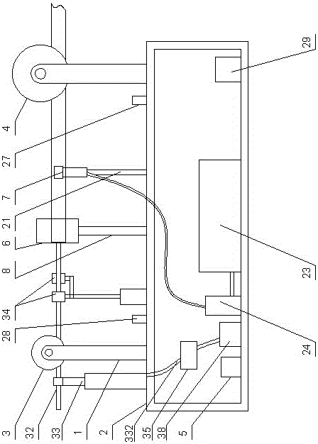
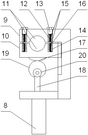
[0034] An on-line deicing device for power transmission lines, including a traveling mechanism and a frame 2 connected below the traveling mechanism through a mechanical arm 1. The wheel 3 and the front road wheel 4 stuck on the ice-covered part of the power transmission line 32, the deicing mechanism is set on the frame 2, and the deicing mechanism is located between the rear road wheel 3 and the front Between the walking wheels 4, a wireless controller 5 is arranged on the left side inside the frame 2, and the traveling mechanism is electrically connected to the wireless controller 5; the deicing mechanism includes ice-coated crushing modules in sequence from left to right 6 and the water knife division module 7; the frame 2 is provided with a drying mechanism for drying the power transmission line 32 and a spraying mechanism 33 arranged at the rear of the drying mechanism and used for spraying water-repellent agent.
[0035] The drying mechanism includes a drying module 34 ...
Embodiment 2
[0045] It differs from Embodiment 1 in that: the water tank 23 is provided with a water inlet, the water inlet is connected with a water pipe 25, and the lower end of the water pipe 25 is connected with a quick joint 26, and the quick joint 26 is used to connect to the water tank on the ground. A water pump is used to add water to the water tank 23.
[0046] In this embodiment, a water inlet is provided on the upper part of the water tank, and the water inlet is connected with a water pipe, and the lower end of the water pipe is connected to the water pump on the ground through a quick joint, so that the water tank can be filled through the water pipe as required, thereby increasing the online capacity of the trolley. Working hours; the water-repellent agent adopted in this embodiment pressurizes the material storage tank by an air pump, then the water-repellent agent in the material storage tank is delivered to the spray nozzle through the paint pipe at its lower part, and an ...
Embodiment 3
[0048] The difference between it and the second embodiment is that: the center of gravity adjustment module is arranged at the bottom of the frame 2, and the center of gravity adjustment module includes a counterweight 30 that is slidingly arranged at the bottom of the frame 2 using a dovetail structure and a counterweight 30 that is arranged on the bottom of the frame 2. 2 The automatic telescopic rod 31 on the left side of the bottom, the free end of the automatic telescopic rod 31 is connected with the counterweight 30, and the automatic telescopic rod 31 is connected with the wireless controller 5 by electrical signals.
[0049] The automatic telescopic rod 31 is an electric telescopic rod.
[0050] In this embodiment, a center-of-gravity adjustment module is provided at the bottom of the frame to adjust the center of gravity of the trolley, so as to avoid the instability of the center of gravity from affecting the work of the trolley; The position of the block can be used...
PUM
 Abstract
Description
Claims
Application Information
 - R&D
- Intellectual Property
- Life Sciences
- Materials
- Tech Scout
- Unparalleled Data Quality
- Higher Quality Content
- 60% Fewer Hallucinations
Browse by: Latest US Patents, China's latest patents, Technical Efficacy Thesaurus, Application Domain, Technology Topic, Popular Technical Reports.
© 2025 PatSnap. All rights reserved.Legal|Privacy policy|Modern Slavery Act Transparency Statement|Sitemap|About US| Contact US: help@patsnap.com


