
A three-position switch mechanism door interlocking device

A three-position switch and door interlock technology, which is applied to air switch parts and other directions, can solve the problems of overshooting of the load switch moving knife, overshoot of the three-position switch, and burnout of the load switch, so as to prolong the service life, Avoiding misjudgment and avoiding the effect of force deformation

Active Publication Date: 2019-05-17
NANJING NARI GROUP CORP
View PDF4 Cites 0 Cited by
  • Summary
  • Abstract
  • Description
  • Claims
  • Application Information

AI Technical Summary

Problems solved by technology

In this type, when the main switch is opened, due to the inertia, the moving knife of the load switch will overshoot, and then the distance between the moving knife of the load switch and the static knife of the grounding switch will become smaller, making the distance between the moving knife and the static knife Arcing causes burnout of the load switch
[0003] There is also a three-position switch composed of a spring mechanism and a gear transmission mechanism, which mainly includes a motor and a transmission component. If the motor cannot stop in place, it will cause the three-position switch to overshoot, which will cause machine failure;
[0005] (3) The status indicating device works only through the gear reduction mechanism, and the structure is not simple enough

Method used


Image

  • A three-position switch mechanism door interlocking device
  • A three-position switch mechanism door interlocking device
  • A three-position switch mechanism door interlocking device

Examples


Embodiment Construction

[0038] The present invention will be further described below in conjunction with the accompanying drawings. The following examples are only used to illustrate the technical solution of the present invention more clearly, but not to limit the protection scope of the present invention.

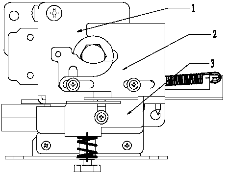
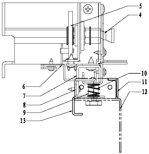
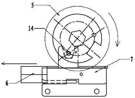
[0039] The invention provides a door interlocking device of a three-position switch mechanism, which includes an operating handle, a disc willow pin 14, a frame body 1, an interlocking baffle 3, a grounding spindle 4, a disc 5, an interlocking sliding baffle 6, Interlocking bent plate 7, interlocking support plate 8, interlocking pin 9, return spring 10 and cable chamber door plate 12;

[0040] The tail end of the grounding spindle 4 extends into the frame 1 through the front side wall of the frame 1, and the head end of the grounding spindle 4 is rotatably connected to the front side wall of the frame 1. A long hole matching the operating handle is provided at the axis of the grounding spindle...


PUM


Abstract

The invention relates to a door interlocking device for a three-station switching mechanism, and belongs to the technical field of switching devices. A separating brake and a grounding operating end are integrated in the door interlocking device, and the structure is simple. A disc is rotated through an operating handle to drive an interlocking sliding baffle to move transversely to relieve constraint on an interlocking baffle, then the interlocking baffle drives a cable chamber door sheet to be opened or closed under the action of a reset spring, operation interlocking of the three-station switching mechanism is achieved, and the flexibility and safety in the working process of the door interlocking device are guaranteed; when the cable chamber door sheet is opened, the interlocking baffle clamps a grounding main shaft to prevent misoperation of a technician, and the device is well protected. The device is rigorous in structural design, an interlocking bent plate has a limiting effect on the interlocking baffle when the cable chamber door sheet is opened, and it is prevented that the interlocking baffle drives the cable chamber door sheet to overshoot, and consequently machine breakdown is caused.

Description

technical field [0001] The invention relates to a door interlocking device of a three-position switch mechanism, which belongs to the technical field of switch devices. Background technique [0002] The three-position switch mechanism disclosed in the prior art includes a front plate and a rear plate fixedly connected by a support column, the output shaft, the main switch operating shaft and the grounding switch operating shaft are all arranged between the front plate and the rear plate, and the opening The spring is arranged between the main switch operating shaft and the grounding switch operating shaft. In this type, when the main switch is opened, due to the inertia, the moving knife of the load switch will overshoot, and then the distance between the moving knife of the load switch and the static knife of the grounding switch will become smaller, making the distance between the moving knife and the static knife Arcing causes the load switch to burn out. [0003] There...

Claims


Application Information

Patent Timeline
Patent Type & Authority Patents(China)
IPC IPC(8): H01H31/06
CPCH01H31/06
Inventor 吕泽峰吴夕科韩冬黄靖宗清森李传强
Owner NANJING NARI GROUP CORP
Learn More