Touch panel and mobile terminal
A touch panel and conductive layer technology, applied in optics, instruments, electrical and digital data processing, etc., can solve problems such as capacitance change, touch function failure, affecting touch function, etc., to prevent failure, prevent distance changes, The effect of preventing deformation
- Summary
- Abstract
- Description
- Claims
- Application Information
AI Technical Summary
Problems solved by technology
Method used
Image

Examples
Embodiment 1
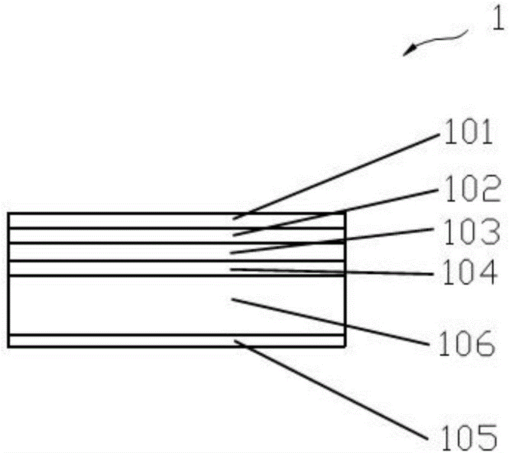
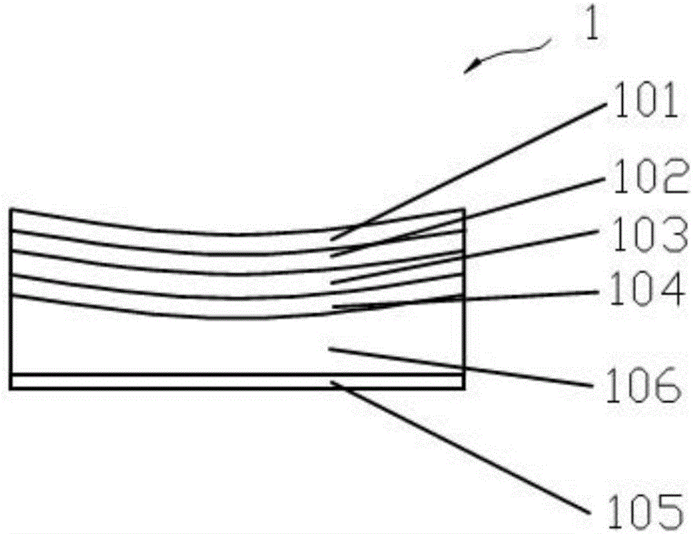
[0027] refer to figure 1 and figure 2 According to the first embodiment of the present invention, the touch panel 1 includes a cover plate 101, a liquid crystal module 102, a backlight module 103, a force-sensing conductive layer 104 and a fixed metal layer 105, wherein the cover plate 101 is arranged on the liquid crystal module 102 on the side away from the backlight module 103, and the liquid crystal module 102 and the backlight module 103 are sequentially stacked on the force-sensing conductive layer 104, and the fixed metal layer 105 is located on the side of the force-sensing conductive layer 104 away from the backlight module 103 The fixed metal layer 105 is, for example, the metal middle frame of the touch panel 1, a capacitor is formed between the force-sensing conductive layer 104 and the fixed metal layer 105, and a spacer layer 106 is provided between the force-sensing conductive layer 104 and the fixed metal layer 105, The spacer layer 106 is filled with elastic...
Embodiment 2
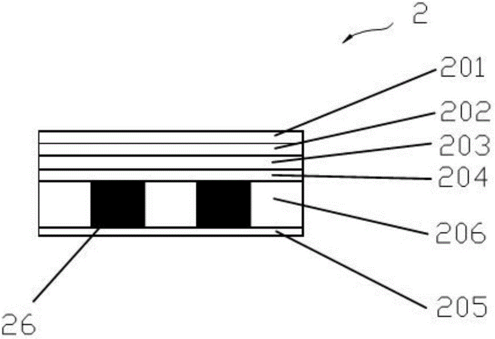
[0031] refer to image 3 and Figure 4 According to the first embodiment of the present invention, the touch panel 2 includes a cover plate 201, a liquid crystal module 202, a backlight module 203, a force-sensing conductive layer 204 and a fixed metal layer 205, wherein the cover plate 201 is arranged on the liquid crystal module 202 on the side away from the backlight module 203, and the liquid crystal module 202 and the backlight module 203 are sequentially laminated on the force-sensing conductive layer 204, and the fixed metal layer 205 is located on the side of the force-sensing conductive layer 204 away from the backlight module 203 The fixed metal layer 205 is, for example, the metal middle frame of the touch panel 2, a capacitor is formed between the force-sensing conductive layer 204 and the fixed metal layer 205, and a spacer layer 206 is provided between the force-sensing conductive layer 204 and the fixed metal layer 205, The spacer layer 206 is filled with elast...
Embodiment 3
[0035] refer to Figure 5 and Image 6 , shows a touch panel 3 according to a third embodiment of the present invention, the touch panel 3 is an in-cell touch panel, and the touch panel 3 includes a cover plate 301, a liquid crystal module 302, a backlight module 303, a force The induction conductive layer 304, the fixed metal layer 305 and the spacer layer 306, wherein the cover plate 301 is arranged on the side of the liquid crystal module 302 away from the backlight module 303, and the liquid crystal module 302 and the backlight module 303 are sequentially stacked on the spacer layer 306 The force-sensing conductive layer 304 is formed in the liquid crystal module 302, and the fixed metal layer 305 is located on the side of the spacer layer 306 away from the backlight module 303. The fixed metal layer 305 is, for example, the metal middle frame of the touch panel 3, and the force A capacitor is formed between the inductive conductive layer 304 and the fixed metal layer 305...
PUM
 Abstract
Description
Claims
Application Information
 - R&D
- Intellectual Property
- Life Sciences
- Materials
- Tech Scout
- Unparalleled Data Quality
- Higher Quality Content
- 60% Fewer Hallucinations
Browse by: Latest US Patents, China's latest patents, Technical Efficacy Thesaurus, Application Domain, Technology Topic, Popular Technical Reports.
© 2025 PatSnap. All rights reserved.Legal|Privacy policy|Modern Slavery Act Transparency Statement|Sitemap|About US| Contact US: help@patsnap.com