
Electro-proportional flow distribution method and system

Active Publication Date: 2018-08-14
XCMG CONSTR MACHINERY
View PDF10 Cites 0 Cited by
  • Summary
  • Abstract
  • Description
  • Claims
  • Application Information

AI Technical Summary

Problems solved by technology

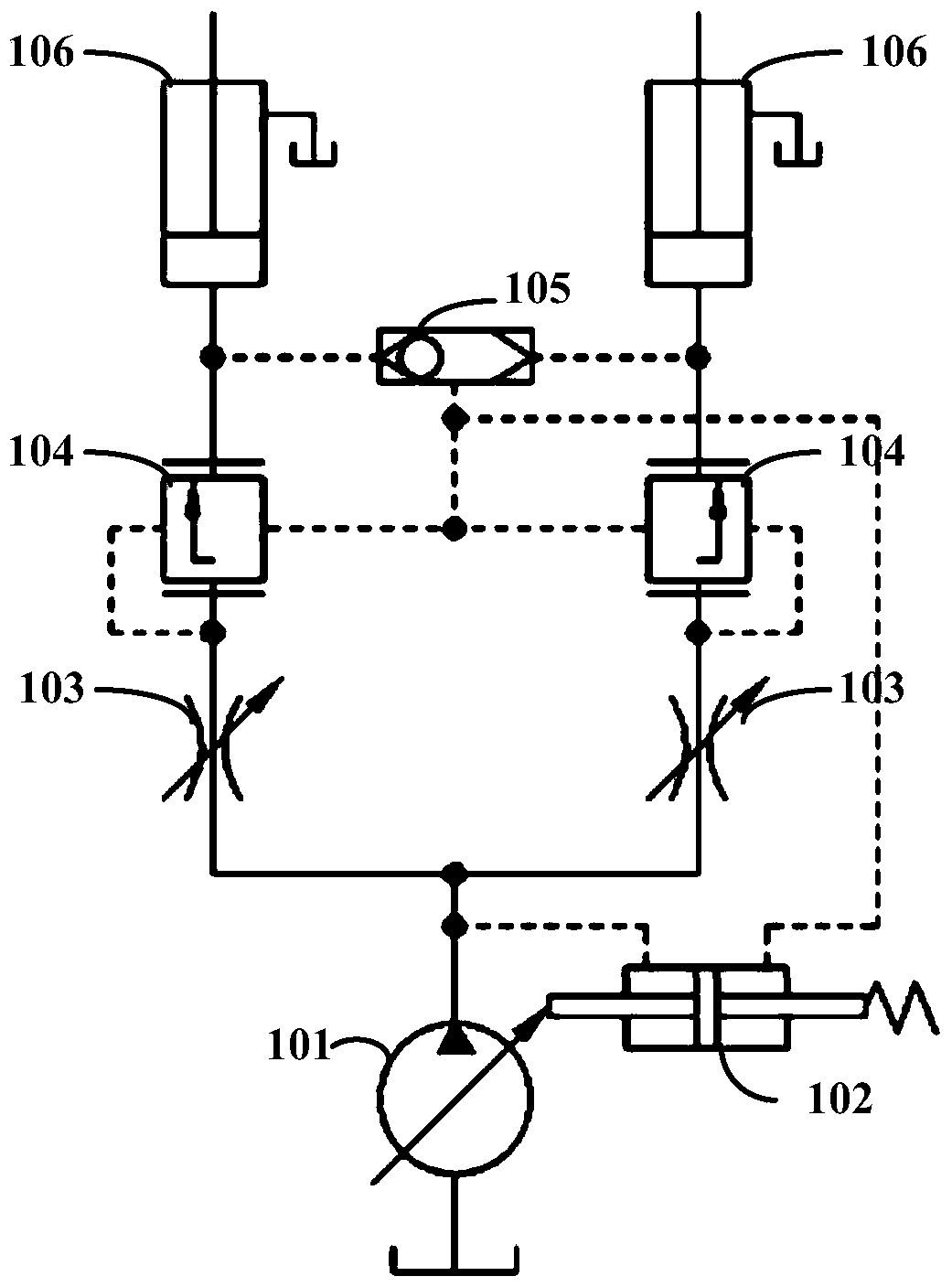
Among them, the flow of each channel of the traditional system is affected by the load, and it is impossible to realize the on-demand distribution independent of the load; although the proportional type can realize the flow of the sub-oil circuit has nothing to do with the load, it can only be distributed according to a fixed ratio, and cannot be freely distributed on demand. And the accuracy is not high; the schematic diagram of the variable ratio is as follows figure 1 As shown, it usually includes a variable pump 101, a variable piston 102, a variable throttle valve 103, a pressure compensation valve 104 and a shuttle valve 105. The highest load pressure of each channel is selected by the shuttle valve 105, and fed back to the variable piston 102 to drive the variable pump 101. Adjust the displacement to meet the flow requirements of the actuator 106, but this method is realized by hydraulic control, the flow adjustment is lagging, and the flow distribution is open-loop control, coupled with the influence of machining accuracy and wear, the accuracy is low, Complex structure and high cost

Method used


Image

  • Electro-proportional flow distribution method and system
  • Electro-proportional flow distribution method and system
  • Electro-proportional flow distribution method and system

Examples


Embodiment Construction

[0040] The following will clearly and completely describe the technical solutions in the embodiments of the present invention with reference to the accompanying drawings in the embodiments of the present invention. Obviously, the described embodiments are only some, not all, embodiments of the present invention. The following description of at least one exemplary embodiment is merely illustrative in nature and in no way taken as limiting the invention, its application or uses. Based on the embodiments of the present invention, all other embodiments obtained by persons of ordinary skill in the art without creative efforts fall within the protection scope of the present invention.

[0041] The relative arrangements of components and steps, numerical expressions and numerical values ​​set forth in these embodiments do not limit the scope of the present invention unless specifically stated otherwise.

[0042] figure 2 It is a schematic diagram of an embodiment of the electric pr...


PUM


Abstract

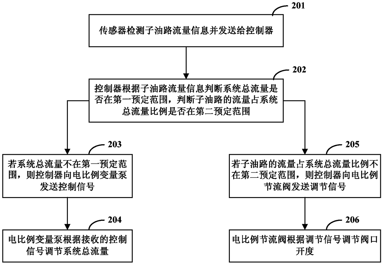
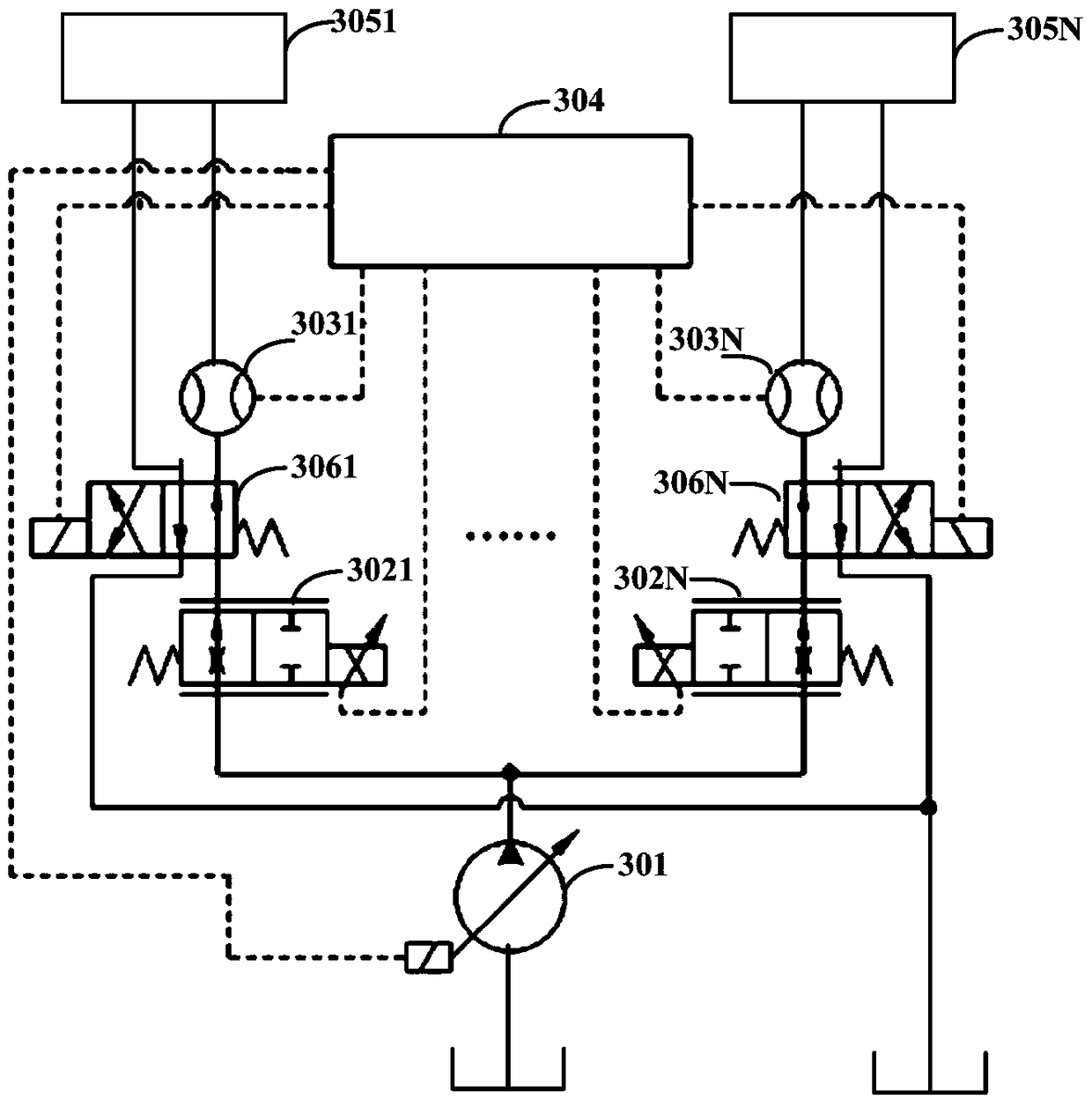
The invention discloses a method and system for electric proportional flow quantity distribution. The method for the electric proportional flow quantity distribution comprises the steps that a sensor detects sub-oil way flow quantity information and sends the information to a controller; the controller judges whether a total flow quantity of the system stays within a first preset scope according to the received sub-oil way flow quantity information, wherein a control signal is sent to an electric proportional variable pump if the total flow quantity of the system does not stay within the first preset scope; the electric proportional variable pump adjusts the total flow quantity of each oil way according to the received control signal; and the controller judges whether the proportion of the sub-oil way flow quantity in the total flow quantity of the system stays within a second preset scope, wherein an adjustment signal is sent to an electric proportional throttle valve on a sub-oil way if the proportion does not stay within the second preset scope, so that the electric proportional throttle valve can adjust valve aperture and distribute the flow quantity of the sub-oil way in proportion. According to the invention, flow distribution which is based on a demanded proportion and irrelevant with loads can be achieved; and the total flow quantity of the system can be adjusted automatically according to demands.

Description

technical field [0001] The invention relates to the field of engineering machinery, in particular to an electric proportional flow distribution method and system. Background technique [0002] Multi-actuator hydraulic systems are widely used in construction machinery, industrial automation and other fields. Usually, the main oil circuit of a single pump is divided into multiple sub-oil circuits to realize the compound action of multiple actuators, which requires a reasonable distribution of the system flow. However, the load borne by each actuator is often uneven, and the flow tends to be in the small load oil circuit, which causes the flow rate of the small load oil circuit to be too large, and the flow rate of the heavy load oil circuit is relatively small, and the flow cannot be distributed according to demand, especially in In the case of insufficient flow (the flow provided by the hydraulic pump cannot meet the requirements of the actuator), the above problems are more...

Claims


Application Information

Patent Timeline
Patent Type & Authority Patents(China)
IPC IPC(8): F15B13/02
Inventor 左帅胡传正刘勇
Owner XCMG CONSTR MACHINERY
Learn More