
Fuel regulating pump with washing device on throttling portion

A technology for fuel conditioning and flushing devices, applied in fuel injection pumps, fuel injection devices, charging systems, etc., can solve the problems of small diameter, easy accumulation in the oil circuit, cleaning of the internal structure of lubricating oil, etc. The effect of blocking, avoiding blocking, saving fuel

Inactive Publication Date: 2017-01-11
CHONGQING KAILONG TECH
View PDF1 Cites 2 Cited by
  • Summary
  • Abstract
  • Description
  • Claims
  • Application Information

AI Technical Summary

Problems solved by technology

[0004] The above-mentioned invention patents solve some problems, but there are certain defects in the design of the internal pipeline of the throttling part. The design of the internal grooves of the throttling part in the scheme is all integrally formed on the steel structure, and the diameter of each groove is very small , cannot be cleaned separately, and it is also difficult to clean the internal structure with lubricating oil. The iron filings generated by the friction between the structures or some impurities in the fuel itself are easy to accumulate in the oil circuit, which will cause the entire throttling part and even the entire fuel oil to be damaged. It is difficult to adjust the pump to work normally, which will affect the power of the fuel injection device and the entire engine

Method used


Image

  • Fuel regulating pump with washing device on throttling portion
  • Fuel regulating pump with washing device on throttling portion

Examples


Embodiment Construction

[0017] The present invention will be described in further detail below by means of specific embodiments:

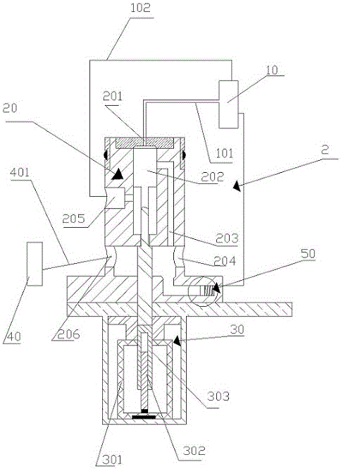
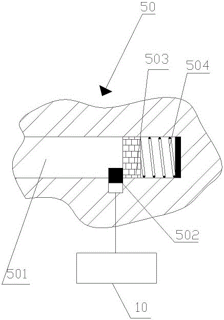
[0018] The reference signs in the drawings of the description include: fuel regulating pump 10, oil pump pipe 101, oil return pipe 102, throttling part 2, suction area 20, oil filling port 201, regulating valve 202, oil inlet groove 203, oil return hole 204, Oil return tank 205, oil outlet hole 206, low pressure zone 30, cylinder barrel 301, air pressure piston 302, piston rod 303, oil injection device 40, oil outlet pipe 401, repeated flushing device 50, oil storage pipe 501, control valve 502, piston 503, Spring 504.

[0019] The embodiment is basically as attached figure 1 And attached figure 2 Shown: a fuel regulating pump 10 with a flushing device on the throttling part 2, including a fuel regulating pump 10, a throttling part 2, a pump oil pipe 101 and a fuel return pipe 102, and the fuel regulating pump 10 connects with the throttling oil through the pump oil pi...


PUM


Abstract

The invention relates to the field of internal combustion engines and particularly discloses a fuel regulating pump with a washing device on a throttling portion. The fuel regulating pump comprises a fuel regulating pump body, the throttling portion, an oil pumping pipe and an oil return pipe. One end of the oil return pipe is fixedly connected with the throttling portion, and the other end of the oil return pipe is fixedly connected with the fuel regulating pump body. The throttling portion comprises a low-pressure region, a suction region and a regulating valve sliding in the low-pressure region and the suction region. One end of the regulating valve is arranged in the suction region, and the other end of the regulating valve is arranged in the low-pressure region. An oil storage chamber, an oil inlet tank, an oil filling opening, an oil return tank and an oil outlet hole are arranged in the suction region. The fuel regulating pump body is fixedly connected with the oil filling opening in the top of the throttling portion through the oil pumping pipe. The oil inlet tank, the oil return tank and the oil outlet hole communicate with the oil storage chamber to form a cavity. The regulating valve is opposite to the oil filling opening. The throttling portion is provided with the repeated washing device. According to the scheme, the repeated washing device is arranged on the oil inlet tank of the throttling portion, and an oil way in the throttling portion is prevented from being clogged.

Description

technical field [0001] The invention belongs to the field of internal combustion engines, in particular to a fuel regulating pump with a flushing device on a throttling part. Background technique [0002] The function of the fuel pump is to suck the fuel out of the fuel tank, pressurize it, and deliver it to the fuel supply pipe. The fuel pump and the fuel pressure regulator cooperate to establish a certain fuel pressure. It is one of the basic components of the fuel injection system of an EFI vehicle. In order to allow the fuel to mix with air quickly, it is necessary to inject a sufficient amount of fuel in a very short time. At this time, the fuel pressure regulating valve is required to increase the fuel injection pressure, so that a sufficient amount of fuel can be injected and mixed with air for rapid combustion. [0003] Patent No. CN103270289A invention patent discloses a pressure regulating device with a fuel injection system for internal combustion engines operated...

Claims


Application Information

Patent Timeline
Patent Type & Authority Applications(China)
IPC IPC(8): F02M59/34F02M59/46F02M59/44F02B77/04
CPCF02M59/34F02B77/04F02B2077/045F02M59/44F02M59/46
Inventor 涂国荣徐飞林锋周玉明涂鑫豪
Owner CHONGQING KAILONG TECH
Learn More