
A waste edge online coiling device for aluminum processing equipment

A technology of coiling device and aluminum processing, applied in metal processing equipment, shearing device, accessory device of shearing machine, etc., can solve the problems of uniformity, inability to guarantee constant tension of waste strips, waste of coiling space, etc.

Active Publication Date: 2019-03-05
涿神有色金属加工专用设备有限公司
View PDF9 Cites 0 Cited by
  • Summary
  • Abstract
  • Description
  • Claims
  • Application Information

AI Technical Summary

Problems solved by technology

The existing coiling device cannot perform on-line coiling. It is necessary to pre-guid and stack the cut waste strips in a certain area of ​​the rolling mill, and then coil them. This not only cannot ensure the constant tension of the waste strips, but also has It may affect the shearing quality of the finished strip, and even cause waste products; and it occupies the surrounding area of ​​the rolling mill, which causes the tension of the surrounding area of ​​the rolling mill, which does not conform to the principle of compact design of the rolling mill; and the axial diameter of the scrap scrap coil cannot be guaranteed Uniformity, wastes the coiling space, and brings troubles to the follow-up processing of waste trim rolls

Method used


Image

  • A waste edge online coiling device for aluminum processing equipment
  • A waste edge online coiling device for aluminum processing equipment
  • A waste edge online coiling device for aluminum processing equipment

Examples


Embodiment Construction

[0017] The present invention will be further described below in conjunction with the accompanying drawings and specific embodiments.

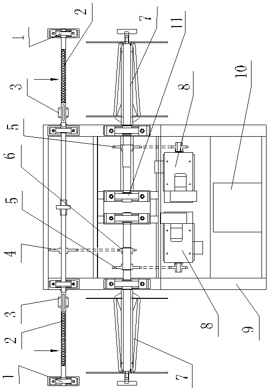
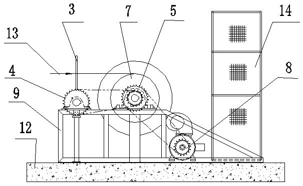
[0018] Such as figure 1 , figure 2 , Figure 4 , Figure 5 , Figure 6 , Figure 7 , Figure 8 and Figure 9 As shown, this embodiment includes a frame 9, a control cabinet 10, and two sets of coiling devices (it can also be one set. When one set is used, the coiling efficiency is low, and it can only be used in conjunction with a waste edge shearing machine that works on one side) . Two groups of coiling devices are installed on the frame 9 oppositely. Each set of winding devices includes a torque motor 8, a winding shaft 7 and a guide device 2. The frame 9, the torque motor 8 and the control cabinet 10 are fixed on the foundation 12. The mandrel of take-up shaft 7 is hinged on the frame 9 through two bearing blocks 11 . The guiding device 2 includes a bidirectional recirculating lead screw 16 , a frame guide frame 3 , a slide blo...


PUM

PropertyMeasurementUnit
thicknessaaaaaaaaaa

Abstract

The invention discloses an on-line winding device for the waste edge for aluminum processing equipment. A mandrel of a winding shaft is hinged to a rack. A bidirectional circulating lead screw is characterized in that two thread lines of the same specification and opposite in screwing directions are correspondingly arranged in the middle of a guide shaft. A sliding block is fixed to a bottom face of a frame type guide frame, and a hole with the diameter matched with the maximum outer diameter of the bidirectional circulating lead screw is formed in the sliding block. A circular-arc guide block is fixedly arranged on the upper end wall of the hole. When the bidirectional circulating lead screw is sleeved with the sliding block, the circular-arc guide block is embedded into a threaded groove in the bidirectional circulating lead screw. An output chain wheel of a torque motor is connected with a drive chain wheel A of the winding shaft through a chain. A middle chain wheel is arranged on the winding shaft. The middle chain wheel is arranged on a drive chain wheel B on the bidirectional circulating lead screw through the chain in a connected manner. By means of the on-line winding device for the waste edge for the aluminum processing equipment, the waste edge is evenly wound around the winding shaft, it is guaranteed that the tension in the waste edge winding process is constant, the edge shearing quality of finished product strips is guaranteed, the yield is increased, the waste edge is wound on line, and the production efficiency is improved.

Description

technical field [0001] The invention relates to a waste edge coiling device used on-line for aluminum processing equipment. Background technique [0002] The waste edge produced by the disc shearing in the aluminum processing equipment needs to be treated. At present, there are mainly two treatment methods. The first is the crushing method, which uses a crusher to crush the waste edge and then transports it to the waste box for centralized processing; affected by the crushing tool material and the structure of the crusher, this method is only suitable for strips with a thickness of 0.5-2mm. If the strip is too thick, it cannot be put into the crusher, and if it is too thin, it cannot be transported into the crusher. Therefore, it is not suitable for strips that are too thin or too thick. The second method is to coil the waste edge, and the coiled material roll is transported to the place where the edge is processed for post-unloading treatment. The existing coiling device ...

Claims


Application Information

Patent Timeline
Patent Type & Authority Patents(China)
IPC IPC(8): B65H54/28B65H59/38B65H67/04B23D33/00B23Q11/00
CPCB23D33/00B23Q11/00B65H54/2818B65H59/385B65H67/0411B65H2701/37
Inventor 许立明刘志岚马镇甲
Owner 涿神有色金属加工专用设备有限公司
Learn More