Wood floor cutter for building decoration
A wood floor and cutting machine technology, which is applied to sawing components, sawing equipment, clamping devices, etc., can solve the problems of not being able to cut different shapes of wood floors according to needs, small application scope, inconvenient transportation, etc. The effect of cutting quality, improving work efficiency and improving stability
- Summary
- Abstract
- Description
- Claims
- Application Information
AI Technical Summary
Problems solved by technology
Method used
Image
Examples
Embodiment 1
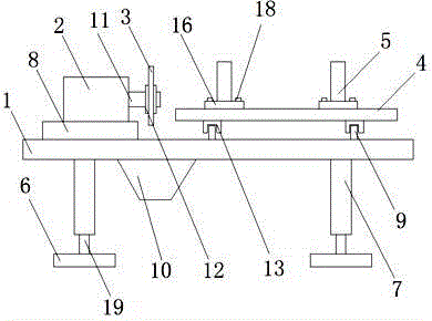
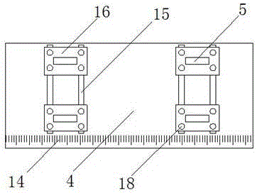
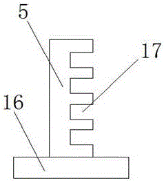
[0021] as attached Figure 1-3 As shown, a wooden floor cutting machine for building decoration, including an operating table 1, a motor 2, a cutting wheel 3, a shifting plate 4, a positioning plate 5 and a backing plate 6, is characterized in that: the operating table 1 is set There are footings 7, fixed plates 8, guide rails 9, and chip collection grooves 10. The motor 2 is arranged on the fixed plate 8, and a drive shaft 11 is arranged on the motor 2. The cutting wheel 3 passes through the mounting block 12 It is arranged on the transmission shaft 11, and the cutting wheel 3 is set as a replaceable structure on the transmission shaft 11 through the mounting block 12. The shift plate 4 is provided with a slider 13, a scale 14, and a limit groove 15 , and the slider 13 is connected with the guide rail 9, the displacement plate 4 is set as a structure capable of moving on the guide rail 9 through the slider 13, and the positioning plate 5 is provided with a bearing plate 16 an...
Embodiment 2
[0029] as attached Figure 4 and 5 Shown, a kind of wooden floor cutting machine for building decoration, comprises operating table 1, motor 2, cutting wheel 3, displacement plate 4, positioning plate 5, backing plate 6, cylinder 20 and pressure plate 22, it is characterized in that: The operating table 1 is provided with feet 7, a fixed plate 8, a guide rail 9, and a chip collection groove 10. The motor 2 is arranged on the fixed plate 8, and a transmission shaft 11 is provided on the motor 2. The cutting The wheel 3 is arranged on the transmission shaft 11 through the installation block 12, and the cutting wheel 3 is set to a replaceable structure on the transmission shaft 11 through the installation block 12. The shift plate 4 is provided with a slide block 13, a scale 14. Limiting groove 15, bearing frame 21, and slide block 13 is connected with guide rail 9, and described displacement plate 4 is set as the structure that can move position on guide rail 9 through slide bl...
PUM
 Abstract
Description
Claims
Application Information
 - R&D
- Intellectual Property
- Life Sciences
- Materials
- Tech Scout
- Unparalleled Data Quality
- Higher Quality Content
- 60% Fewer Hallucinations
Browse by: Latest US Patents, China's latest patents, Technical Efficacy Thesaurus, Application Domain, Technology Topic, Popular Technical Reports.
© 2025 PatSnap. All rights reserved.Legal|Privacy policy|Modern Slavery Act Transparency Statement|Sitemap|About US| Contact US: help@patsnap.com


