
A method for winding a stator, as well as a stator and an electric machine with such a stator

A stator and winding technology, applied in the manufacture of motor generators, the shape/style/structure of winding conductors, windings, etc., can solve problems such as winding short circuit and motor locking

Active Publication Date: 2017-01-04
ROBERT BOSCH GMBH
View PDF8 Cites 1 Cited by
  • Summary
  • Abstract
  • Description
  • Claims
  • Application Information

AI Technical Summary

Problems solved by technology

There is a risk that, for example, if the insulation varnish of the winding wires is damaged, a short circuit in the winding can occur, which leads to a blocking of the motor

Method used


Image

  • A method for winding a stator, as well as a stator and an electric machine with such a stator
  • A method for winding a stator, as well as a stator and an electric machine with such a stator
  • A method for winding a stator, as well as a stator and an electric machine with such a stator

Examples


Embodiment Construction

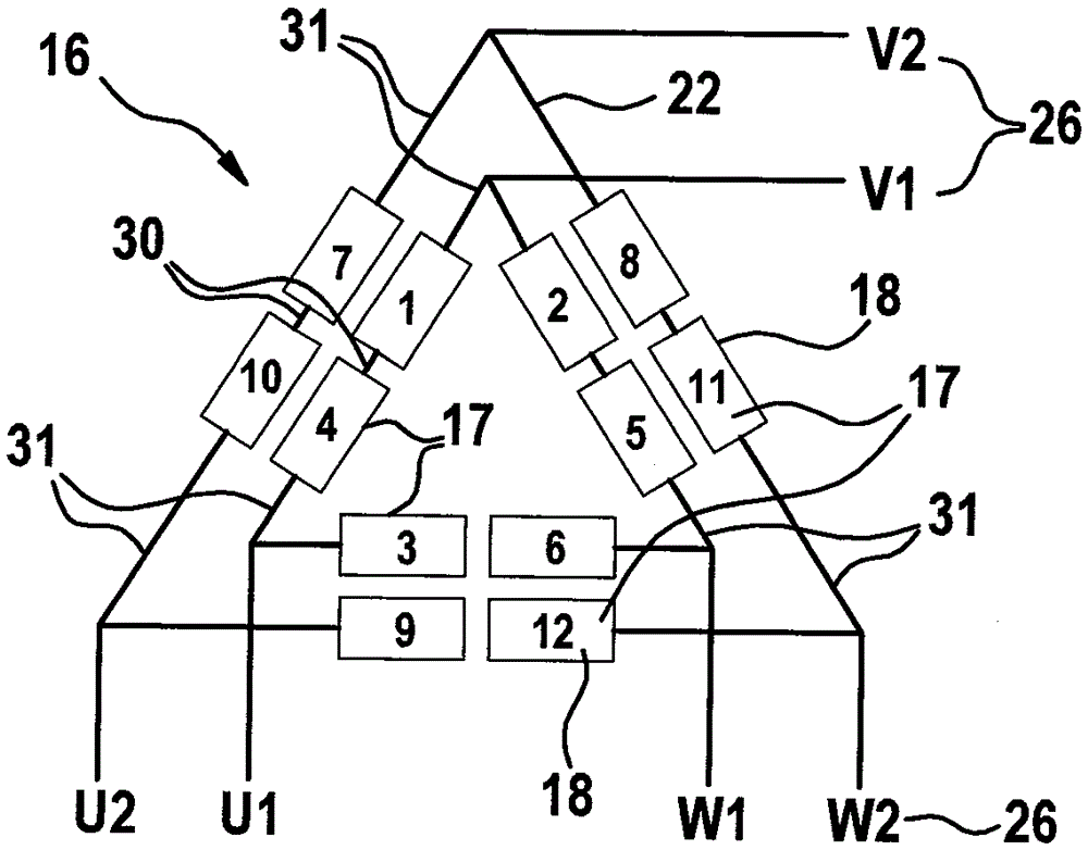
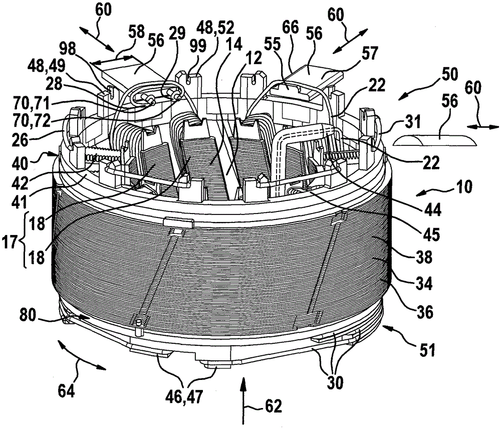
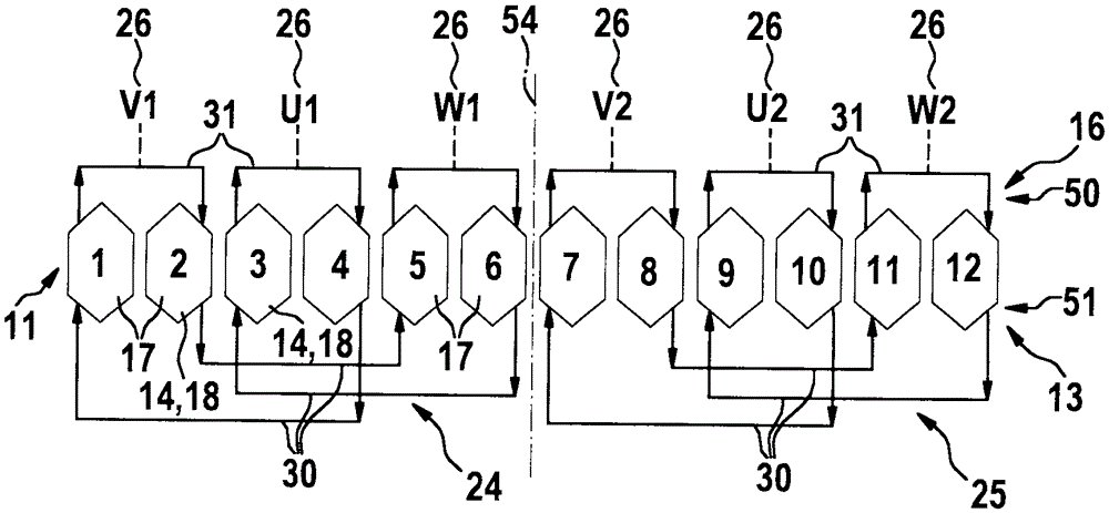
[0022] exist figure 1 The stator 10 is shown schematically in cross section, and the winding diagram of the electrical winding 16 according to the invention is shown on its stator teeth 14 . The stator 10 has, for example, twelve stator teeth 14 , wherein exactly one partial coil 18 is always wound on each stator tooth 14 . In this case, every two sub-coils 18 directly next to each other are connected on the first axial side 50 of the stator 10 by means of short connecting lines 31 to form an adjacent sub-coil pair 17 , which in this exemplary embodiment each form its own phase. 26V1, U1, W1, V2, U2, W2. The three phases 26V1 , U1 , W1 here form their own winding phases 24 , which are wound by separate winding conductors 22 . The three phases 26V2, U2, W2 form a second winding phase 25, which is wound by a second independent winding wire 22 and is electrically insulated from the first winding phase 24, as by figure 1As shown by the dashed-dotted line 54 between the sixth an...


PUM


Abstract

The invention provides a method for winding a stator (10), as well as a stator and an electric machine with such a stator. The stator (10) comprises radial stator teeth (14) and grooves (12) between the stator teeth; a first sub-coil (18) is wound around a first stator tooth (14) by using needle type winding; a connecting wire (31) is wound via a radially-movable slider (56) close to a first axial end face (50) of the stator (10) to form a second sub-coil (18) of a second stator tooth (14); then the slider (56) is removed; the connecting wire (31) is fixed in at least one clamping element (48) of the stator (10).

Description

technical field [0001] The present invention relates to a method for winding a stator as claimed in the independent claims, as well as to a stator and an electric machine comprising such a stator. Background technique [0002] From DE 10 2012 224 153 A1, a stator for an electric machine is known, in which insulating laminations and connecting disks are arranged axially on the lamination stack. The stator is wound, for example, with needle-coils, wherein the individual sub-coils are connected to one another on the outer circumference of the connection disk by means of connecting lines. The entire winding is wound continuously in one piece with a single winding wire. [0003] For safety-critical applications of electric machines, eg in power steering machines, the inherent safety of such electrical windings is still under discussion. There is the risk that, for example, if the insulating varnish of the winding wire is damaged, a short circuit of the winding can occur, which ...

Claims


Application Information

Patent Timeline
Patent Type & Authority Applications(China)
IPC IPC(8): H02K15/085H02K3/50H02K3/28
CPCH02K3/28H02K3/50H02K15/085H02K3/522H02K15/095
Inventor M.佩施T.斯索蒂
Owner ROBERT BOSCH GMBH
Learn More