
Wireless electric energy transmission device based on two polar plate virtual ground structures by utilizing capacitive coupling

A technology of wireless power transmission and capacitive coupling, applied in circuit devices, electric vehicle charging technology, electrical components, etc., can solve the problems of difficulty in making high-frequency power supplies, small coupling capacitance, and increased high-frequency resistance, so as to solve the surrounding environment. The required limit, the operating frequency is stable, the effect of the low decay rate

Inactive Publication Date: 2017-01-04
WUHAN UNIV
View PDF2 Cites 10 Cited by
  • Summary
  • Abstract
  • Description
  • Claims
  • Application Information

AI Technical Summary

Problems solved by technology

Capacitive power transmission only uses metal plates, which have the advantages of good conductivity, low price, and light weight; while the coils for inductive power transmission must be wound with Litz wire, which is relatively expensive, which is very unfavorable for wireless power transmission the popularity of
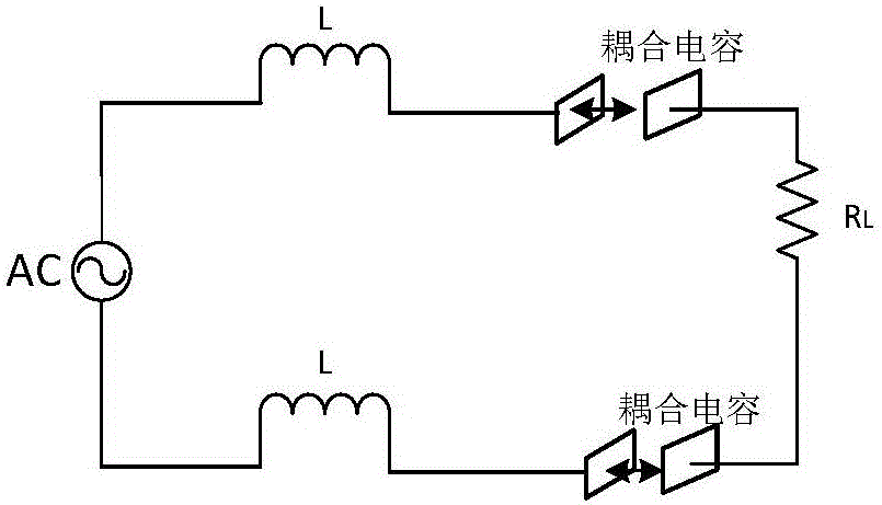
However, the typical capacitive power transmission circuit has the following two disadvantages (such as figure 1 ): As the transmission distance increases, the coupling capacitance value becomes very small, which makes the system resonance frequency increase seriously; and at very high frequencies, the high-frequency power supply required by the system is difficult to manufacture, and the high-frequency resistance increases sharply. leading to a sharp decline in the overall efficiency of the system
Therefore, the wireless power transmission system based on the traditional capacitive transfer model is difficult to achieve long-distance power transmission

Method used


Image

  • Wireless electric energy transmission device based on two polar plate virtual ground structures by utilizing capacitive coupling
  • Wireless electric energy transmission device based on two polar plate virtual ground structures by utilizing capacitive coupling
  • Wireless electric energy transmission device based on two polar plate virtual ground structures by utilizing capacitive coupling

Examples


Embodiment Construction

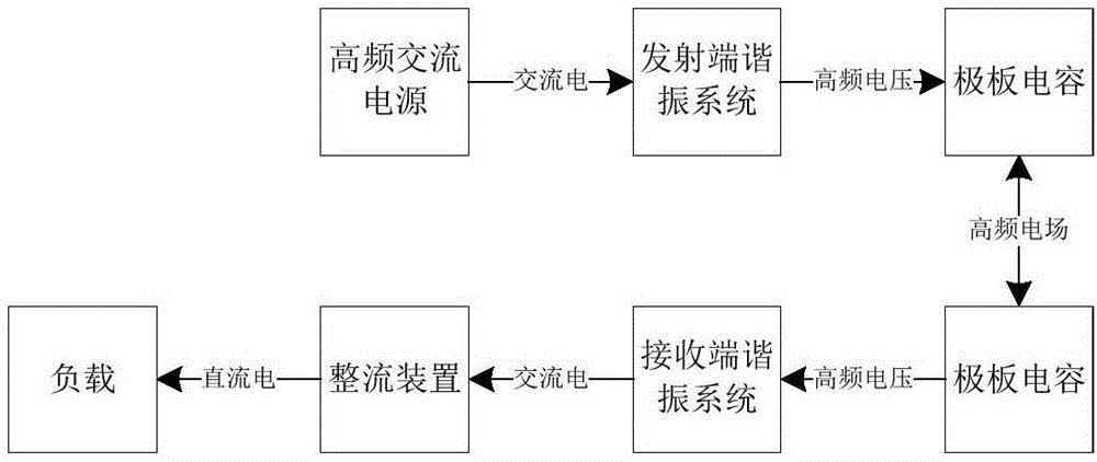
[0021] Such as figure 2 As shown, the present invention includes four parts: a frequency-adjustable AC power supply, two sets of resonant systems, plate capacitors and two conductors. The transmitter consists of a high-frequency AC power supply, a resonance system at the transmitter, and a plate capacitor C 2 The E plate and conductor 1 are composed; the receiving end is composed of the receiving end resonant system, the plate capacitance C 2 Composed of F board, conductor 2 and load. The transmitter resonant system consists of an inductor L 1 and tuning capacitor C 1 , the high-frequency AC power supply and the resonant system at the transmitter form a series loop, and the plate capacitance C 2 E plate with capacitor C 1 The A terminal is connected, the capacitor C 1 The B end of the terminal is connected to the conductor 1; the resonant system at the receiving end includes the inductance L 3 and tuning capacitor C 3 , the resonant system at the receiving end forms a...


PUM


Abstract

The invention relates to a wireless electric energy transmission device based on two polar plate virtual ground structures by utilizing capacitive coupling. On the basis of analysis on advantages and disadvantages of a typical capacitor electric transmission circuit model, a novel capacitor electric transmission circuit model is designed, and the pair of polar plate capacitors and two conductors are additionally arranged. A high-frequency oscillation system generates high-frequency voltage at the junction of one of the capacitors and an inductor in a resonance state, an induction current is generated by connecting the high-frequency voltage onto the polar plate capacitors, and transfer of capacitance between the polar plate capacitors is realized. Compared with inductive electric transmission, the device has the advantages that the structure is simple, and efficiency attenuation is slower along with extension of distance. Compared with a traditional capacitor electric transmission structure, the advantages of reduction of working frequency and high transmission efficiency can be achieved under remote electric transmission. Through the device, the limitation that inductive electric transmission has requirements for surroundings is well avoided, and the device is more suitable for the situation that surroundings have high metal content, for example, wireless charging of electric cars, mobile phones and tablet computers.

Description

technical field [0001] The invention relates to a high-frequency resonant high-voltage electric field coupling wireless power transmission technology, in particular to a wireless power transmission device based on a two-plate virtual ground structure utilizing capacitive coupling. Background technique [0002] Inductive Power Transfer Technology (IPT) has been widely applied to electric vehicles and mobile terminal equipment, and its transmission efficiency is already comparable to that of traditional wired power transmission. However, the disadvantage of inductive power transmission is that it depends on the conductor medium. When the concentration of metal substances in the air is high, the magnetic field will generate a current vortex, causing energy loss and increasing the temperature, which is very dangerous. Capacitive transmission is a good solution to this problem. [0003] Capacitive power transfer uses an electric field instead of a magnetic field to transfer elec...

Claims


Application Information

Patent Timeline
IPC IPC(8): H02J5/00H02J50/05
CPCH02J5/005Y04S30/12Y02T90/167
Inventor 胡文山周洪高星冉祖爽邓其军
Owner WUHAN UNIV
Learn More