Power unit bypass protection device

A power unit, bypass protection technology, applied in emergency protection circuit devices, electrical components, etc., can solve the problems of difficult component selection and high cost, and achieve the effect of avoiding breakdown damage and solving difficult selection.

Active Publication Date: 2017-01-04
TBEA SUNOASIS +2
View PDF7 Cites 3 Cited by
  • Summary
  • Abstract
  • Description
  • Claims
  • Application Information

AI Technical Summary

Problems solved by technology

[0007] Aiming at the above-mentioned deficiencies in the prior art, the present invention provides a power unit bypass protection device to solve the problems of difficult selection of components and high cost of the existing power unit bypass protection device

Method used


Image

  • Power unit bypass protection device
  • Power unit bypass protection device
  • Power unit bypass protection device

Examples


Embodiment 1

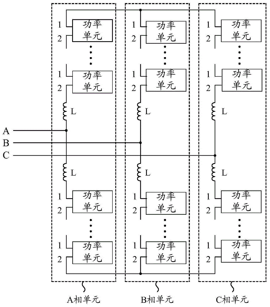
[0045] Embodiment 1 of the present invention provides a power unit bypass protection device, which is applied to a flexible direct current transmission system, and can quickly bypass a failed power unit when a power unit fails. The power unit bypass protection device includes a system controller (not shown in the figure) and a plurality of power units, the plurality of power units according to figure 2 Connected as shown, each power unit adopts a half-bridge sub-module topology.

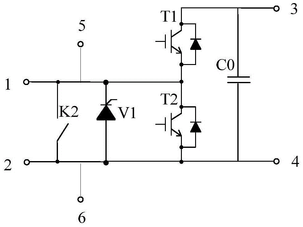
[0046] The following combination Figure 4 , detailing the topology of the power unit. Such as Figure 4 As shown, each power unit includes a switch K2 connected in parallel between the input terminal and the output terminal of the half-bridge sub-module (ie, terminal 1 and terminal 2), and also includes thyristors V1 and V2, and the thyristors V1 and V2 are connected in antiparallel to Between the input and output of the half-bridge sub-module. Wherein, the switch K2 adopts an ordinary mechanic...

Embodiment 2

[0076] Embodiment 2 of the present invention provides a power unit bypass protection device, which is applied to figure 2 In the flexible direct current transmission system shown, each power unit can be quickly bypassed when the system direct current bus is short-circuited. The power unit bypass protection device includes: a flexible direct current transmission system protection switch (not shown in the figure), a system controller (not shown in the figure) and multiple power units. The flexible direct current transmission system protection switch adopts an ordinary mechanical switch . multiple power units according to figure 2 Connected as shown, each power unit adopts a half-bridge sub-module topology.

[0077] The difference between Embodiment 2 and Embodiment 1 is that there is no need to set a switch K2 in each power unit, and the energy harvesting power supply can only output one DC power supply (ie, the first DC power supply).

[0078] The following combination F...


PUM


Abstract

The invention provides a power unit bypass protection device. A common mechanical switch is used to replace a mechanical-type rapid switch with a specific model. Thyristors V1 and V2 are arranged, and a first voltage division circuit and a second voltage division circuit are arranged too. When a power unit has a fault, through driving a thyristor V3 in the first voltage division circuit to be conducted, the thyristor V1 is controlled to be conducted, or through driving a thyristor V4 in the second voltage division circuit to be conducted, the thyristor V2 is controlled to be conducted. Before a switch K2 is closed, the thyristor V1 or the V2 achieves an effect of carrying out short circuit on the fault power unit so as to remove the fault power unit from a flexible direct current power transmission system. After the switch is closed, the switch bypasses the fault power unit. Because response time of the thyristor is less than response time of the common mechanical switch, through using the thyristor, failure response time can be shortened to a nanosecond level so that problems that component type selecting is difficult and cost is high are solved.

Description

technical field [0001] The invention relates to the technical field of high-voltage and high-power power transmission and transformation, in particular to a power unit bypass protection device. Background technique [0002] The flexible DC transmission device is a device that converts AC high voltage and large current into DC high voltage and large current, and transmits electric energy to the terminal through overhead lines or cables, and finally converts DC high voltage and large current into high voltage AC power. Through the flexible direct transmission equipment, the power supply of multiple regions or offshore oil exploitation can be realized, and the transmitted active power and reactive power can be independently and quickly controlled, which greatly enhances the flexibility of power transmission and realizes the interconnection of regional power grids. [0003] At present, the power unit of the flexible DC transmission converter valve can be applied in the flexible ...

Claims


Application Information

Patent Timeline
Patent Type & Authority Applications(China)
IPC IPC(8): H02H7/12
Inventor 雒龙飞刘伟增黎小林许树楷陈名龚文明李直樊文斌
Owner TBEA SUNOASIS
Why Eureka
Try Eureka