
Compact high-directivity wideband TEM horn antenna

A horn antenna, high directional technology, applied in the direction of antenna, waveguide horn, antenna grounding device, etc., can solve the requirement of high processing precision of TEM two-arm curve, not suitable for the working requirements of ground penetrating radar system, and cannot guarantee low-frequency partial directional radiation and other problems, to achieve the effect of compact structure, small volume, and guaranteed directional radiation

Active Publication Date: 2017-01-04
SHANGHAI JIAO TONG UNIV
View PDF2 Cites 4 Cited by
  • Summary
  • Abstract
  • Description
  • Claims
  • Application Information

AI Technical Summary

Problems solved by technology

There are also standard horn antennas or TEM horns, but the size and wavelength are comparable, and the total volume of the antenna is large
[0003] Through literature search, it is found that the patent application number is 201020599359.2, and the patent name is: an ultra-wideband curved surface TEM horn antenna. The patent publication number is CN201956462U. This antenna is used in ultra-wideband radar systems. It is still the conventional size of the TEM horn, and at the same time, it is more sensitive to deformation due to the higher requirements for the machining accuracy of the curves of the two arms of the TEM.
[0004] In the search, it was also found that in 2014, Turniger et al. published "Research and Design of Ultra-Wideband TEM Horn Antenna with Low-frequency Compensation" in the 8th issue of Volume 14 of the "Science Technology and Engineering" journal. The operating frequency can be reduced to a lower level under the condition of daring to increase the size, but it cannot guarantee the stable directional radiation of the low frequency part, which is not suitable for the actual working requirements of the ground penetrating radar system.

Method used


Image

  • Compact high-directivity wideband TEM horn antenna
  • Compact high-directivity wideband TEM horn antenna
  • Compact high-directivity wideband TEM horn antenna

Examples


Embodiment Construction

[0047] The present invention will be described in detail below in conjunction with specific embodiments. The following examples will help those skilled in the art to further understand the present invention, but do not limit the present invention in any form. It should be noted that those skilled in the art can make several changes and improvements without departing from the concept of the present invention. These all belong to the protection scope of the present invention.

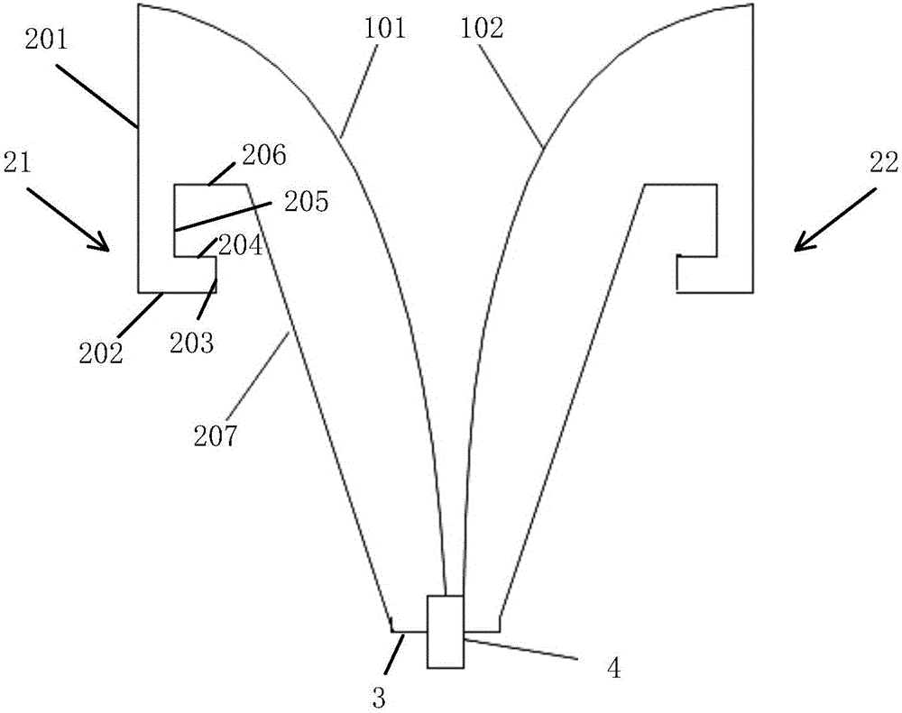
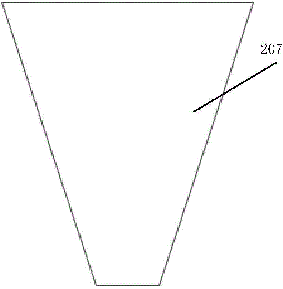
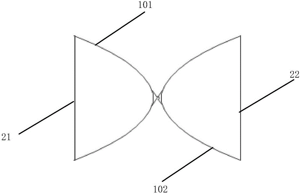
[0048] The invention provides a compact and highly directional broadband TEM horn antenna, comprising: a TEM horn antenna and a feeding port. The TEM horn antenna includes two arms of the TEM antenna and a short-circuit backplane for low-frequency compensation, and the inner core and outer conductor of the feed port are respectively connected to the two arms of the TEM horn. The invention has simple structure and low production cost, can realize very wide working frequency band and stable directional ra...


PUM


Abstract

The present invention provides a compact high-directivity wideband TEM horn antenna, comprising: a TEM horn antenna and a feed port, wherein the TEM horn antenna comprises two arms of a traditional TEM antenna and a low-frequency-compensation short circuit back plate, and an inner core and an outer conductor of the feed port are connected to the two arms of the TEM antenna respectively. The compact high-directivity wideband TEM horn antenna of the present invention is simple in structure and low in manufacturing cost, can realize a very wide operating frequency band and stable directional radiation on the premise of guaranteeing the size, and can meet the requirements of ground penetrating radars under different conditions and requirements for system miniaturization, thereby having wide application prospects.

Description

technical field [0001] The present invention relates to a TEM horn antenna, in particular to a compact and highly directional broadband TEM horn antenna, especially a broadband directional TEM horn antenna with low-frequency compensation, which works in the VHF / UHF frequency band, has a stable pattern, and can be applied in the field of ground penetrating radar. Background technique [0002] In the prior art, ground-penetrating radars use symmetrical array antennas such as dish antennas. The size of such antennas is usually half of the wavelength. At the same time, a back cavity needs to be added to ensure the directional radiation of the antenna. The bandwidth of this type of antenna is limited. There are also standard horn antennas or TEM horns, but the size and wavelength are comparable, and the total volume of the antenna is very large. [0003] After literature search, it is found that the patent application number is 201020599359.2, and the patent name is: an ultra-wi...

Claims


Application Information

Patent Timeline
Patent Type & Authority Applications(China)
IPC IPC(8): H01Q13/02H01Q5/55H01Q1/48
CPCH01Q1/48H01Q5/55H01Q13/02
Inventor 周晗耿军平梁仙灵王栋任超凡金荣洪
Owner SHANGHAI JIAO TONG UNIV
Learn More