
Database switching method and system

A technology for switching systems and databases, applied in database design/maintenance, database distribution/replication, structured data retrieval, etc., can solve problems such as long downtime, achieve fast switching speed, easy implementation, and high switching efficiency

Inactive Publication Date: 2017-01-04
HEFEI MIDEA INTELLIGENT TECH CO LTD
View PDF6 Cites 8 Cited by
  • Summary
  • Abstract
  • Description
  • Claims
  • Application Information

AI Technical Summary

Problems solved by technology

[0006] In order to solve the problems of too long downtime and the need for manual solutions when the existing database fails, the present invention provides a database switching method and system, which solves the above problems from the perspective of mutual switching between identical and real-time synchronized dual databases , which greatly reduces the downtime, improves the efficiency of database switching, and enables the application server to resume work quickly and automatically

Method used


Image

  • Database switching method and system

Examples


Embodiment 1

[0043] Specifically, the database switching method of the present invention includes the following steps,

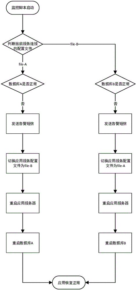
[0044] Step 1, build a database system with dual databases. In this embodiment, the dual databases include database A and database B; the present invention can be widely applied to various intelligent refrigerators, so the database system can be a database disaster recovery system for refrigerators .

[0045] Step 2, the script with monitoring function is started. In this embodiment, the analysis shows that database A is working. Through the analysis of configuration file file-A, it is found that database A is working. The configuration file file-A points to database A. At this time, the application server Establish communication with database A through the configuration file file-A. Of course, the working database may also be database B, and this step of the present invention is only to illustrate that a database is working in the double database, such as figure 1 As ...

Embodiment 2

[0053] The database switching method of the second embodiment is basically the same as that of the first embodiment, the difference being that in step 4, when the database A fails, the method of establishing communication between the application server and the database B is different. In this embodiment, during the process of switching from database A to database B, an alarm message and / or email is sent to the operator, and database B obtains the virtual IP address of database A, so that the configuration file file-A points to database B, and the application server configures File file-A establishes communication with database B.

[0054] The invention also discloses a database switching system, which includes database A, database B, an application server and a control server. The database A and database B are the same database, and under the action of the control server, the control server automatically sends a monitoring , switching and other commands, the application server...


PUM


Abstract

The invention discloses a database switching method and system. The switching method comprises the steps as follows: firstly, a database system with two databases is built; next, the fact that the database A is operating is obtained through analysis; then, the database A is monitored, and the database A is switched to the database B if the database A is abnormal. The switching system comprises the database A, the database B, an application server and a control server, wherein the database A and the database B are identical, and the application server is connected with the database A or the database B under the action of the control server. The abnormity of the databases can be detected automatically, intelligent switching can be performed timely when the databases are abnormal, and the downtime of the application server is greatly shortened; when the databases are abnormal, automatic switching instead of manual processing can be performed, so that the manual workload is reduced; besides, operating workers are informed and reminded of abnormity in the first time through messages or mails.

Description

technical field [0001] The present invention relates to the technical field of databases, and more specifically, to a database switching method and system. Background technique [0002] Database disaster recovery, the full name of database disaster backup, refers to the process of copying the entire system or part of the data set from the hard disk or array of the application host to other storage media in order to prevent data loss caused by operational errors or system failures. The traditional database disaster There are mainly two solutions as follows. [0003] (1) There is only one application database, and only when problems such as database paralysis occur, problems are manually solved. Although this method is simple and easy to implement, if a sudden failure occurs, it is difficult for the entire system to respond and repair in time, and the application server will not work normally for a long time, and the downtime will be very long. [0004] (2) Master-slave back...

Claims


Application Information

Patent Timeline
Patent Type & Authority Applications(China)
IPC IPC(8): G06F17/30G06F11/14
CPCG06F16/27G06F11/1458G06F16/21G06F2201/80
Inventor 王云陈
Owner HEFEI MIDEA INTELLIGENT TECH CO LTD
Learn More