Solar energy light condensation structure

A solar concentrator and heat collector technology, applied in the field of solar energy utilization, can solve problems such as light pollution and heat loss, and achieve the effects of reducing heat loss, uniform heating, and restraining air flow.

Active Publication Date: 2017-01-04
SUZHOU NUCLEAR POWER RES INST +2
View PDF17 Cites 4 Cited by
  • Summary
  • Abstract
  • Description
  • Claims
  • Application Information

AI Technical Summary

Problems solved by technology

However, whether it is point focusing or line focusing, the reflector will not choose the angle of incident light and reflected light, which will cause light pollution, and the air flow around the collector will make heat loss unavoidable

Method used


Image

  • Solar energy light condensation structure
  • Solar energy light condensation structure
  • Solar energy light condensation structure

Examples


Embodiment 1

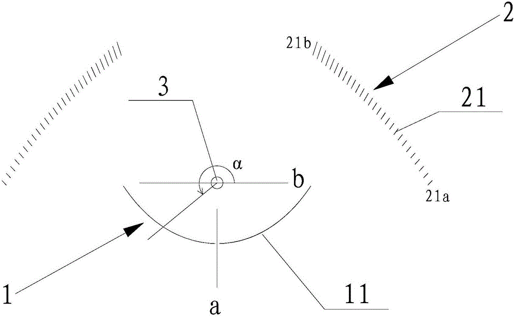
[0017] Such as figure 1 The solar concentrating structure shown is a linear concentrating structure, which mainly includes three parts: a first reflector 1 , a Fresnel reflector group 2 and a heat collector 3 .

[0018] Wherein, the heat collector 3 is arranged at the focal point of the first reflector 1, and the sunlight can be focused to the lower surface of the heat collector 3 by the first reflector 1 (the definition of the relevant direction here is according to figure 1 The direction in is defined, the same below). There is at least one group of Fresnel reflector groups 2 , which are arranged on the other side of the heat collector 3 (that is, above the first reflector 1 ), and are used to focus sunlight onto the surface of the heat collector 3 . Each group of Fresnel reflector groups 2 is formed by arranging a plurality of reflectors 21 with different angles in turn, and the symmetry plane passing through the heat collector 3 in the first reflector 1 is defined as its ...

Embodiment 2

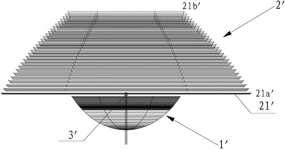
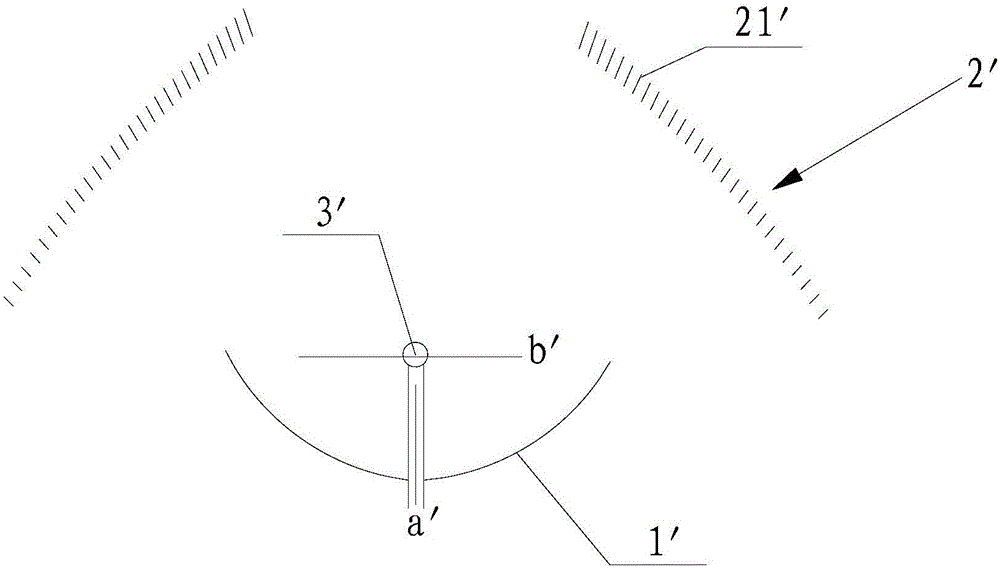
[0022] Such as figure 2 and image 3 The solar concentrating structure shown is a point concentrating structure, and mainly includes three parts: the first reflector 1', the Fresnel reflector group 2' and the heat collector 3', and its specific structure and embodiment The structure in 1 is basically similar, the difference is that: the first reflector 1' is a spherical mirror; the Fresnel reflector group 2' is a group, which consists of a plurality of concentrically arranged annular reflectors 21' arranged sequentially from bottom to top. become.

[0023] In this embodiment, the radius of the heat collecting surface of the first reflecting mirror 1' can be 2025mm (here, the size of the solar concentrating structure is just an example, and its specific size can be scaled); the heat collector 3' is a Stirling machine Advanced heat collection system, the heat collection tube adopts a spherical double helix structure to increase the heating area. Similarly, the sunlight withi...


PUM


Abstract

The invention relates to a solar energy light condensation structure which comprises a first reflector and a heat collector arranged at a light condensation focus of the first reflector. The solar energy light condensation structure is characterized by further comprising at least one set of Fresnel reflection team arranged on the other side of the heat collector and used for condensing sunlight to the heat collector, wherein the Fresnel reflection team is formed by sequentially arranged a plurality of reflector plates with different angles; a symmetry plane, passing through the heat collector, in the first reflector, is defined as a first symmetry plane, and the included angles between the first symmetry plane and the plurality of reflector plates are sequentially increased or decreased. Therefore, the upper and lower surfaces of the heat collector are heated at the same time by reflected light, the heat collector surfaces are mostly high-temperature regions, the heat dissipation area is small, the heat collector surfaces are evenly heated, the air mobility is inhibited, low high-temperature regions are reduced, heat loss is reduced, and no influence is caused on the surrounding circumstance by the reflected light.

Description

technical field [0001] The invention belongs to the technical field of solar energy utilization, and in particular relates to a solar energy concentrating structure. Background technique [0002] The concentrator is an important part of the solar photovoltaic concentrating module. It is mainly used for concentrating power generation. Its concentrating methods are divided into three methods: point focus, line focus and surface focus. [0003] In the point focusing method, the butterfly mirror concentrating system is the most common, and the butterfly system focuses the sunlight on the heat collector of the Stirling engine through the point focusing method; in the online focusing method, the solar parabolic trough thermal power generation system is the most Commonly, trough systems use line focusing to focus sunlight onto tubular collectors. However, whether it is point focusing or line focusing, the reflector will not select the angle of incident light and reflected light, w...

Claims


Application Information

Patent Timeline
Patent Type & Authority Applications(China)
IPC IPC(8): F24J2/10F24J2/24F24S23/70F24S10/70
CPCY02E10/44F24S10/70F24S23/82F24S2023/872
Inventor 张镇滔李强汤桂荣邹平国张文中李刚倪彬彬
Owner SUZHOU NUCLEAR POWER RES INST
Why Eureka
Try Eureka