
Biomass circulating fluidized bed boiler slagging device

A circulating fluidized bed and biomass technology, which is applied in the direction of fluidized bed combustion equipment, fuel burned in molten state, combustion type, etc., can solve problems such as poor fuel adaptability, poor slag discharge, and failure to discharge impurities in biomass , to achieve the effects of reducing emission concentration, reducing energy loss, and reducing pressure head wear

Active Publication Date: 2019-04-05
HANGZHOU BOILER GRP CO LTD
View PDF5 Cites 0 Cited by
  • Summary
  • Abstract
  • Description
  • Claims
  • Application Information

AI Technical Summary

Problems solved by technology

[0005] The technical problem to be solved by the present invention is to provide a biomass circulating fluidized bed boiler slagging device, which solves the problems caused by the combustion of various biomass and fuel mixed with large inert materials in the biomass fuel circulating fluidized bed boiler. Poor fuel adaptability, poor slag discharge and other problems, it has the technical advantages of uniform air distribution, efficient fuel combustion, less wear on the heating surface, good equipment economy, and high reliability
[0007] A rotating vortex device is added, which can effectively screen the materials, so that large pieces of materials and sundries can be discharged smoothly through the large slag discharge pipe, which solves the problem that the impurities of the biological materials cannot be discharged, and effectively prevents the long-term accumulation of impurities, causing the wind cap and slag discharge device blockage, to ensure long-term continuous and safe operation of boiler equipment

Method used


Image

  • Biomass circulating fluidized bed boiler slagging device
  • Biomass circulating fluidized bed boiler slagging device

Examples


Embodiment Construction

[0021] The present invention will be further described below with reference to the accompanying drawings.

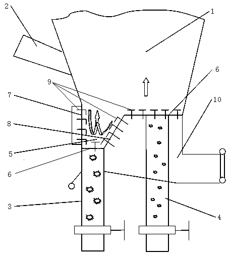
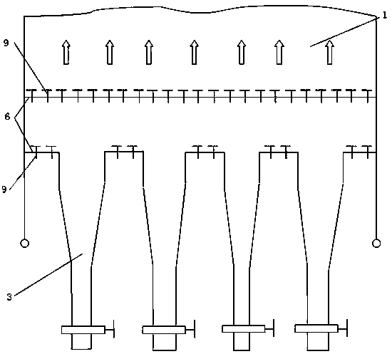
[0022] Such as Figure 1-2 As shown, the biomass circulating fluidized bed boiler slagging device provided in this embodiment includes a combustion chamber 1, a furnace feeding device 2 is connected above the combustion chamber 1, and a large slag is provided below the combustion chamber 1. The slag discharge pipe 3 and the crushed slag discharge pipe 4, one side of the bottom of the combustion chamber 1 is a horizontal plate, and the other side is a single V-shaped screening bucket 5, and the single V-shaped screening bucket 5 is located obliquely below the horizontal plate , the single V-shaped screening bucket 5 includes a vertical part, a horizontal part and an inclined part connected in sequence, the other end of the inclined part is connected with the horizontal plate, the large slag discharge pipe 3 communicates with the horizontal part, and the broken slag discha...


PUM


Abstract

The invention discloses a slag discharging device of a biomass circulating fluidized bed boiler. The slag discharging device of the biomass circulating fluidized bed boiler comprises a combustion chamber, wherein a boiler-front feeding device is connected above the combustion chamber, a large slag discharging pipe and a disintegrating slag discharging pipe are arranged below the combustion chamber, a horizontal plate is arranged on one side of the bottom of the combustion chamber, a single V-shaped screening bucket is arranged on the other side of the bottom of the combustion chamber, and located at the inclined lower part of the horizontal plate, the large slag discharging pipe is communicated with the single V-shaped screening bucket, the disintegrating slag discharging pipe is communicated with the horizontal plate, and a rotating vortex device is arranged in the single V-shaped screening bucket. The slag discharging device of the biomass circulating fluidized bed boiler has the advantages of capability of solving the problems of bad fuel adaptability, unsmooth slag discharging and the like caused by massive inert materials doped in a variety of biomass and fuel combusted by the biomass fuel circulating fluidized bed boiler, and the technical advantages of uniform air distribution, efficient fuel combustion, small abrasion of a heating surface, good equipment economy and high reliability.

Description

technical field [0001] The invention belongs to the technical field of circulating fluidized bed boilers, in particular to a biomass circulating fluidized bed boiler slagging device. Background technique [0002] With the gradual depletion of non-renewable energy resources and the heavy pressure on the ecological environment, people are paying more and more attention to renewable clean energy. Biomass energy is a part of renewable energy, the fourth largest energy in the world, and has become an important research object in renewable energy. Biomass energy is an internationally recognized clean energy. The development of biomass energy has far-reaching social significance and broad market prospects for our country. In terms of our country's basic national conditions and the level of biomass utilization and development, biomass direct combustion technology is undoubtedly the most convenient. One of the feasible and efficient ways to use biomass energy. [0003] The circulat...

Claims


Application Information

Patent Timeline
Patent Type & Authority Patents(China)
IPC IPC(8): F23C10/20F23C10/24
CPCF23C10/20F23C10/24F23C2206/10
Inventor 叶忠李永华刘影任旭峰薛鹏毅刘志
Owner HANGZHOU BOILER GRP CO LTD
Learn More