A double-pit combustor structure for a rotary engine

A rotary engine, double-pit type technology, used in combustion engines, machines/engines, internal combustion piston engines, etc., can solve the problem of not organizing a variety of airflow motion forms, reducing ignition reliability at the rear of the combustion chamber, and unfavorable oil and gas mixing. and ignition problems, so as to optimize the distribution law of the in-cylinder flow field, optimize the distribution law, and achieve the effect of stratification.

Inactive Publication Date: 2019-04-02
JIANGSU UNIV
View PDF6 Cites 0 Cited by
  • Summary
  • Abstract
  • Description
  • Claims
  • Application Information

AI Technical Summary

Problems solved by technology

[0002] Because the structure of the combustion chamber of the current rotary engine is too simple, coupled with the fact that the rotor continuously rotates in one direction in the cylinder, the airflow in the combustion chamber mainly flows in one direction along the movement direction of the rotor, and does not organize various forms of airflow movement On the one hand, the unidirectional flow field distribution in the cylinder of the rotary engine is not conducive to the mixing and ignition of oil and gas, and on the other hand, it is also not conducive to the movement of the combustion flame front to the rear of the combustion chamber, resulting in difficulty in mixing oil and gas, reducing ignition reliability and burning The problem of difficult combustion of the mixture in the rear of the chamber

Method used


Image

  • A double-pit combustor structure for a rotary engine
  • A double-pit combustor structure for a rotary engine
  • A double-pit combustor structure for a rotary engine

Examples


Embodiment Construction

[0020] The present invention will be further described below in conjunction with the accompanying drawings.

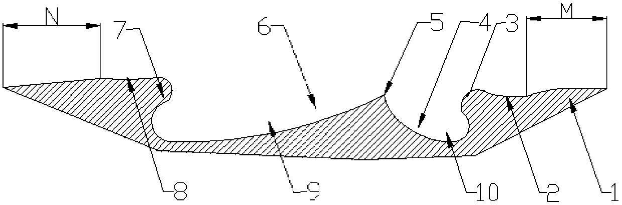
[0021] Such as figure 1 As shown, the double-pit type combustion chamber for the rotary engine according to the present invention includes: the front transition arc 2, the front neck 3, the front guide wall 4, the middle inclined guide table 5, and the rear guide wall 6 , Rear necking 7, Rear transition arc 8. The rear dimple 9 is composed of a rear guide wall 6 and a rear constriction 7 , and the front dimple 10 is composed of a front constriction 3 and a front guide wall 4 .

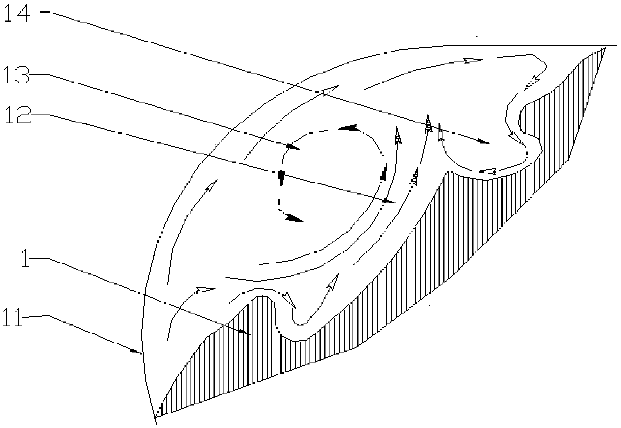
[0022] Such as figure 2 As shown, in the compression stroke of the rotary engine, combined with the intake inertia, under the guidance of the front shrinkage 3 and the front guide wall 4, a compression front vortex 14 is generated in the front dimple 10, and the rear guide wall 6 and Under the guidance of the rear constriction 7, a post-compression vortex 13 is generated in the rear dimple ...


PUM


Abstract

The invention belongs to the field of internal combustion engine structural design and particularly relates to a double-pit type combustion chamber structure for a rotor engine. The double-pit type combustion chamber structure for the rotor engine is characterized in that a front transition arc, a front pit, a middle oblique flow guide table, a rear pit and a rear transition arc are sequentially arranged on the surface of a triangular rotor in the direction opposite to the rotor rotating direction; the front pit specifically comprises a front necking part and a front flow guide wall; the rear pit specifically comprises a rear flow guide wall and a rear necking part; the front flow guide wall is located in front of the middle oblique flow guide table, the rear flow guide wall is located behind the middle oblique flow guide table, the front necking part is designed at the front end of the front flow guide wall, and the rear necking part is designed at the rear end of the rear flow guide wall. The combustion efficiency of the rotor engine can be improved.

Description

technical field [0001] The invention belongs to the field of internal combustion engine structure design, and in particular relates to a double-pit combustion chamber structure suitable for a rotary engine. Background technique [0002] Because the structure of the combustion chamber of the current rotary engine is too simple, coupled with the fact that the rotor continuously rotates in one direction in the cylinder, the airflow in the combustion chamber mainly flows in one direction along the movement direction of the rotor, and does not organize various forms of airflow movement On the one hand, the unidirectional flow field distribution in the cylinder of the rotary engine is not conducive to the mixing and ignition of oil and gas, and on the other hand, it is also not conducive to the movement of the combustion flame front to the rear of the combustion chamber, resulting in difficulty in mixing oil and gas, reducing ignition reliability and burning The problem of difficu...

Claims


Application Information

Patent Timeline
Patent Type & Authority Patents(China)
IPC IPC(8): F02B55/14
CPCF02B55/14
Inventor 潘剑锋刘洪俊范宝伟陈伟
Owner JIANGSU UNIV
Why Eureka
Try Eureka