A crankcase pressure self-balancing system for aviation heavy oil piston engine

A technology of piston engine and crankcase, applied in crankcase ventilation, engine components, machine/engine, etc., can solve the problems of polluting the environment, polluting the environment, increasing oil consumption, etc., to increase service life and improve intake air quality , to ensure the effect of stable work

Active Publication Date: 2019-02-22
北京领动国创科技有限公司
View PDF7 Cites 0 Cited by
  • Summary
  • Abstract
  • Description
  • Claims
  • Application Information

AI Technical Summary

Problems solved by technology

When the engine runs at high speed, a large amount of mist oil will be produced, and the mist oil will flow out of the crankcase along with the airflow through the sheet, increasing the consumption of engine oil; if the discharged oily gas directly enters the atmosphere, it will inevitably pollute the environment and make the engine discharge exceed the Relevant standards; if the exhausted oily gas enters the cylinder for combustion, since the engine oil cannot be completely burned, a large amount of engine oil or the products of incomplete combustion of the engine oil will still enter the atmosphere, which will also pollute the environment
In addition, many gasoline engines use hoses to directly connect the inner chamber of the crankcase with the atmosphere. Although the pressure difference between the inner and outer chambers of the crankcase can be reduced to a certain extent, the intake and exhaust volume and the intake and exhaust speed cannot be controlled, and it is impossible to achieve oil and gas separation

Method used


Image

  • A crankcase pressure self-balancing system for aviation heavy oil piston engine
  • A crankcase pressure self-balancing system for aviation heavy oil piston engine
  • A crankcase pressure self-balancing system for aviation heavy oil piston engine

Examples


Embodiment Construction

[0039] The present invention will be further described in detail below in conjunction with the accompanying drawings.

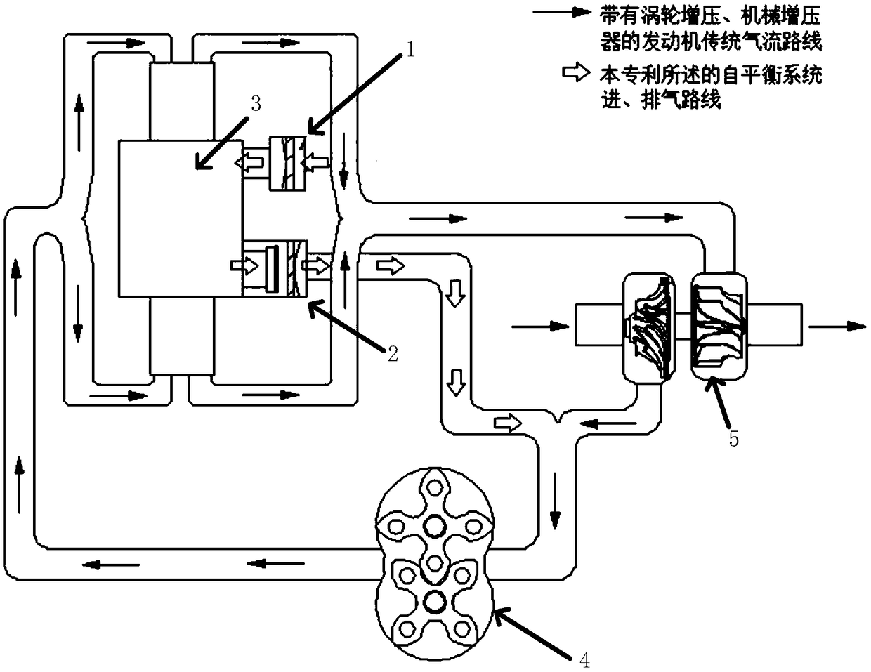
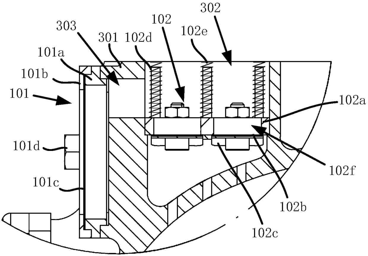
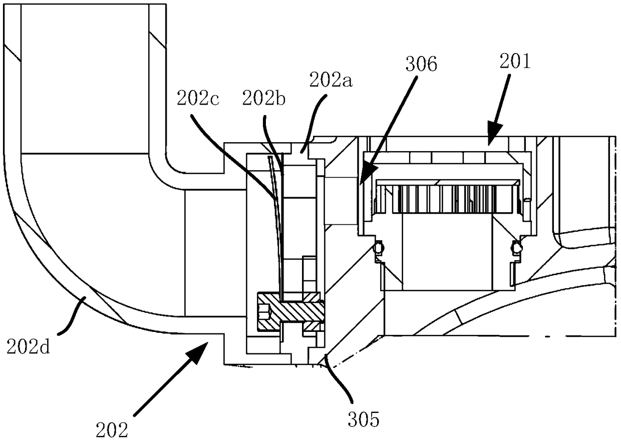
[0040] The present invention is used in the crankcase pressure self-balancing system of the aviation heavy oil piston engine. On the basis of the traditional engine gas circulation path equipped with the supercharger 4 and the turbocharger 5, a crankcase air intake system 1 and a crankcase air intake system are added. Exhaust system 2, such as figure 1 shown. The crankcase air intake system 1 and the crankcase exhaust system 2 use the crankcase 3 as an assembly base, wherein the crankcase air intake system 1 includes a crankcase air inlet assembly 101 and a front air intake mechanical assembly 102, such as figure 2 Shown; Crankcase exhaust system 2 comprises oil-gas separation assembly 201, crankcase air outlet assembly 202, as image 3 shown.

[0041] In the crankcase intake system 1, the crankcase intake assembly 101 includes a crankcase intake joint 10...


PUM


Abstract

The invention discloses a crankcase pressure self-balancing system for an aviation heavy oil piston engine, which can realize self-balance of internal pressure of the aviation heavy oil piston engine. The internal pressure of a crankcase fluctuates, and correspondingly decreases and increases along with the upward movement and downward movement of a piston. The self-balance refers to that the crankcase can change according to the internal pressure, when the pressure is reduced, air supply is carried out through a front intake mechanical assembly and a crankcase air inlet assembly, so that the crankcase can automatically supply air or discharge air according to cavity inside and outside pressure differences, that is, the air supply is automatically carried out when the pressure of an inner cavity is reduced, air discharge is carried out when the pressure of the inner cavity is increased, and the self-balance of the pressure in the crankcase is achieved. The crankcase pressure self-balancing system for the aviation heavy oil piston engine has the advantages that the air inflow amount and air discharge amount of the crankcase can be automatically adjusted according to the cavity inside and outside pressure differences, without arranging a sensor or requiring manual intervention, so that the balance of the pressure of the inner cavity and the outer cavity of the crankcase can be automatically realized to ensure the engine moving parts to be stably operated.

Description

technical field [0001] The invention relates to the technical field of aviation heavy oil piston engines, in particular to a crankcase pressure self-balancing system for aviation heavy oil piston engines. Background technique [0002] In recent years, with the continuous development of the engine industry, the market demand for turbocharged engines with low fuel consumption and high output power is increasing. When the supercharged engine is working at low speed and light load, the vacuum in the intake passage is very large, which causes the pressure imbalance in the inner and outer cavities of the crankcase. invalid loss. At the same time, the exhaust gas entering the crankcase will deteriorate the oil and corrode the body. If the exhaust gas is directly discharged into the atmosphere, it will inevitably lead to high fuel consumption and high pollution emissions. Apparently, when the existing supercharged engine is at low speed and light load (or the supercharger is not ...

Claims


Application Information

Patent Timeline
Patent Type & Authority Patents(China)
IPC IPC(8): F01M13/00F01M13/04F02M25/06
CPCF01M13/00F01M13/0011F01M13/0033F01M2013/0005F01M2013/0422F02M25/06
Inventor 周煜杜发荣丁水汀刘勐
Owner 北京领动国创科技有限公司
Why Eureka
Try Eureka