Rotor spinning method
A technology of rotor spinning and rotor spinning, which is applied in the field of spinning, and can solve the problems of low rotor count, unfavorable fiber transfer, and difficulty in yarn formation, so as to enhance twisting efficiency, broaden the scope of application, and reduce broken yarns. head effect
- Summary
- Abstract
- Description
- Claims
- Application Information
AI Technical Summary
Problems solved by technology
Method used
Image
Examples
Embodiment 1
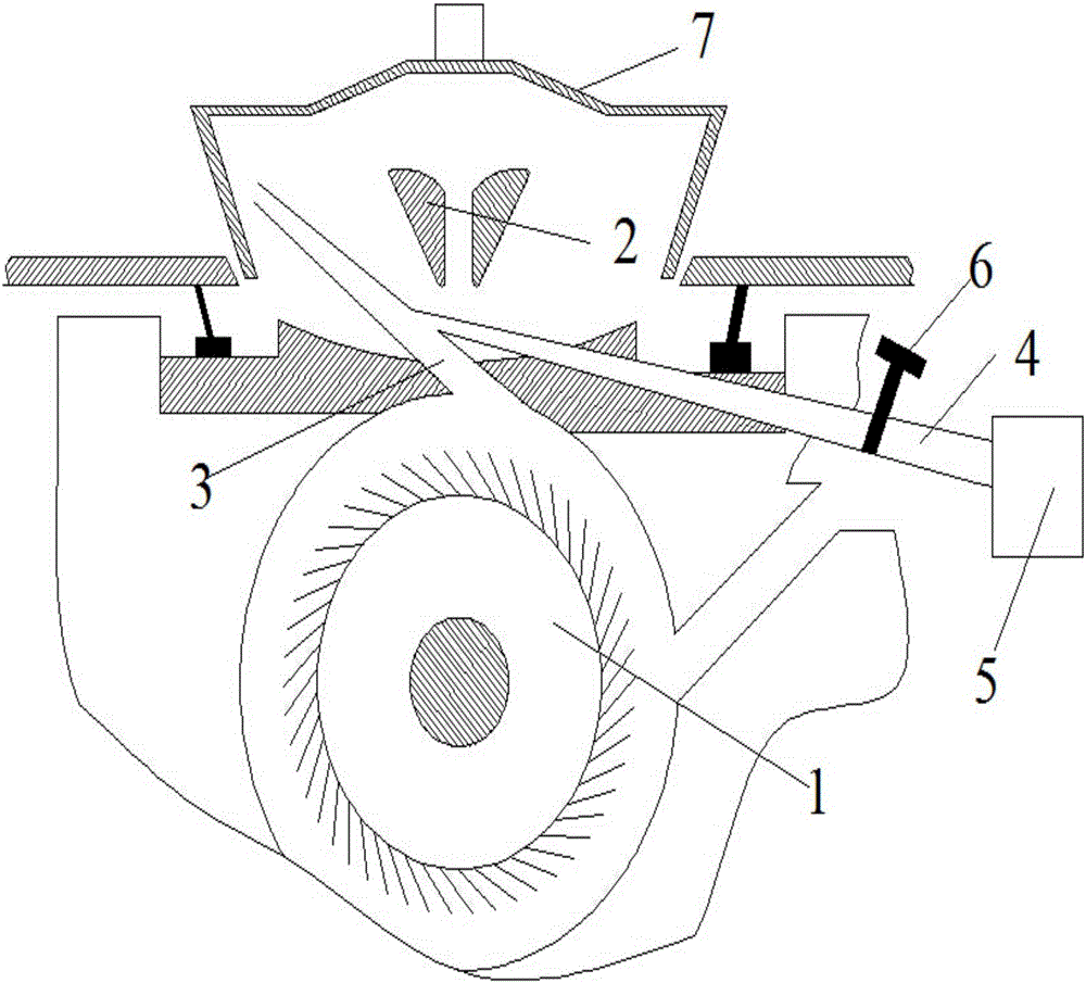
[0026] A rotor spinning method, the spinning process uses a rotor spinning device with adjustable humidity in the rotor, which is used to spin 14.5tex pure combed noil, the structure of the rotor spinning device is as follows figure 1 As shown, it includes a fiber delivery channel 3 and a carding roller 1, and an air supply pipe communicating with the side of the fiber delivery channel 3 that is tangent to the casing of the carding roller is provided between the carding roller 1 and the false twist disc 2 4. The other end of the air supply pipe 4 is connected to the air supply pump 5 that can generate water vapor. There is an opening and closing valve 6 between the air supply pipe 4 and the air supply pump. The fiber delivery channel 3 is a linear tapered channel. In the conveying direction of the fiber in the channel, the diameter of the fiber delivery channel 3 is gradually reduced, and the air supply pipe 4 is a linear tapered channel, and the diameter of the air supply pip...
Embodiment 2
[0029]A rotor spinning method, the spinning process uses a rotor spinning device with adjustable humidity in the rotor, used to spin 14.5tex pure combed noil, the rotor spinning device includes a fiber delivery channel 3 and Carding roller 1, between carding roller 1 and false twist disk 2, be provided with the air supply pipe 4 that is connected with the side that is tangent to the casing of opening roller on fiber delivery channel 3, the other end of air supply pipe 4 is connected with The air supply pump 5 that can generate water vapor is connected. An opening and closing valve 6 is provided between the air supply pipe 4 and the air supply pump. The fiber delivery channel 3 is a linear tapered channel. The diameter of the channel 3 gradually decreases, and the air supply pipe 4 is a linear tapered channel. From the air supply pump to the direction where the air supply pipe connects with the fiber delivery channel, the diameter of the air supply pipe gradually decreases. The ...
Embodiment 3
[0032] A rotor spinning method, the spinning process uses a rotor spinning device with adjustable humidity in the rotor, used to spin 14.6tex pure combed noil, the rotor spinning device includes a fiber delivery channel 3 and Carding roller 1, between carding roller 1 and false twist disk 2, be provided with the air supply pipe 4 that is connected with the side that is tangent to the casing of opening roller on fiber delivery channel 3, the other end of air supply pipe 4 is connected with The air supply pump 5 that can generate water vapor is connected. An opening and closing valve 6 is provided between the air supply pipe 4 and the air supply pump. The fiber delivery channel 3 is a linear tapered channel. The diameter of the channel 3 gradually decreases, and the air supply pipe 4 is a linear tapered channel. From the air supply pump to the direction where the air supply pipe connects with the fiber channel, the diameter of the air supply pipe gradually decreases, and the cros...
PUM
| Property | Measurement | Unit |
|---|---|---|
| diameter | aaaaa | aaaaa |
| elongation at break | aaaaa | aaaaa |
| elongation at break | aaaaa | aaaaa |
Abstract
Description
Claims
Application Information
 - R&D
- Intellectual Property
- Life Sciences
- Materials
- Tech Scout
- Unparalleled Data Quality
- Higher Quality Content
- 60% Fewer Hallucinations
Browse by: Latest US Patents, China's latest patents, Technical Efficacy Thesaurus, Application Domain, Technology Topic, Popular Technical Reports.
© 2025 PatSnap. All rights reserved.Legal|Privacy policy|Modern Slavery Act Transparency Statement|Sitemap|About US| Contact US: help@patsnap.com


