
A method for processing joint parts

A technology for parts processing and parts, applied in the field of joint parts processing, can solve problems such as errors, and achieve the effects of high processing accuracy, improved bearing capacity, and shortened waiting period

Active Publication Date: 2019-05-21
CHENGDU AIRCRAFT INDUSTRY GROUP
View PDF5 Cites 0 Cited by
  • Summary
  • Abstract
  • Description
  • Claims
  • Application Information

AI Technical Summary

Problems solved by technology

It is necessary to turn over and clamp the parts many times, which is easy to cause errors

Method used


Image

  • A method for processing joint parts
  • A method for processing joint parts
  • A method for processing joint parts

Examples


Embodiment 1

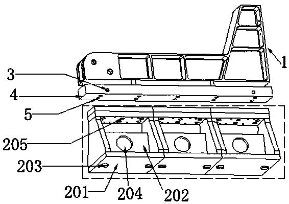
[0037] Such as image 3 Shown: The structure of the upper and lower parts of the joint part 1 is asymmetric; it includes a large number of rib structures and side grooves; the part has a thin-walled structure, and the thickness of the smallest part is only 1.5mm. The part has high machining accuracy and is easy to deform.

[0038] For this joint part 1, the analysis found that the difficulty in processing lies in effectively controlling the deformation generated during the processing of the part, maintaining the stable processing state of the part, reducing the turning and clamping work of the part, reducing the labor intensity of the operator, and improving the processing efficiency. efficiency.

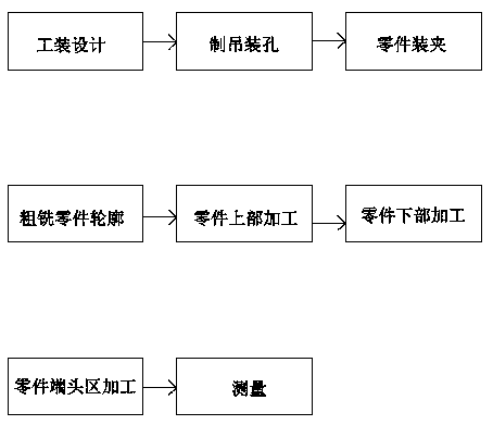
[0039] Concrete processing flowchart of the present invention is as figure 1 shown.

[0040] A. Tooling design: In view of the structural characteristics and machine tool characteristics of the joint parts 1, in order to ensure the processing quality, design special tooling such a...

Embodiment 2

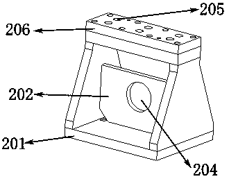
[0050] On the basis of Embodiment 1, preferably, the tooling of the present invention includes an upper surface 206, a base 201 and a reinforcing rib 202; the base 201 includes a bottom surface and two sides perpendicular to the bottom surface; the upper surface 206 and the base 201 is connected in a ring shape; the reinforcing rib 202 is connected between the vertical two sides of the base 201; the reinforcing rib 202 is perpendicular to the vertical two sides; the reinforcing rib 202 is perpendicular to the bottom surface; the bottom surface of the base 201 is provided with The positioning key 203; the reinforcing rib 202 is provided with a lightening hole 204.

Embodiment 3

[0052] On the basis of Embodiment 1, preferably: in step D, in the rough milling part contour step, a three-coordinate general-purpose machine tool is used to ensure that the margin on one side is not less than 10mm, and the contour is cut off. In this way, the weight of the blank can be appropriately reduced, and it is convenient for the workers to clamp; a suitable machining allowance can ensure that the blank itself has good rigidity when the finishing is stripped from the top to the bottom layer, and the blank will not vibrate during the processing, thus ensuring Processing quality of parts.


PUM

PropertyMeasurementUnit
thicknessaaaaaaaaaa

Abstract

The invention discloses a machining method of joint-like parts, and a special tool is designed with the joint-like parts on an airplane as research objects. Blanks are fixed with the tool, deformation in the part machining process is controlled, and the stable machining state of the parts is maintained; and meanwhile, the part turning and clamping operations are reduced, the labor intensity of operators is relieved, and the machining efficiency is improved. Rough milling of part outlines is carried out, the upper portions of the parts are machined, the lower portions of the parts are machined, the tip areas of the parts are machined, and finally measurement is carried out one time. Through the scheme, the problem of part staggering is solved, and the requirement for coaxiality of deep hole machining is ensured. Through measurement, the machining error of the parts is within + / -0.1 mm and is far superior to that of a conventional machining scheme, and meanwhile the machining time is significantly shortened.

Description

technical field [0001] The invention relates to the field of mechanical processing, in particular to a processing method for joint parts. Background technique [0002] Due to the large size and complex structure of aircraft joint parts, it has always been one of the difficulties that plague the CNC machining of aircraft structural parts. In recent years, the research on this kind of parts mainly focuses on how to improve the processing efficiency and precision. The traditional CNC machining method is carried out on a five-coordinate vertical machining center, which is processed after multiple clamping and measurement, which will inevitably cause clamping and positioning errors, so that the precision requirements of the parts cannot be guaranteed, and the processing cycle is relatively long. Therefore, how to improve the machining efficiency and machining accuracy of such parts is very necessary. [0003] The application number is CN200710145927.4, and the name is the inven...

Claims


Application Information

Patent Timeline
Patent Type & Authority Patents(China)
IPC IPC(8): B23P15/00
CPCB23P15/00
Inventor 熊航崔雅文李燕南杨玲
Owner CHENGDU AIRCRAFT INDUSTRY GROUP
Learn More