A compound insert for turning and milling with wave-shaped chip guide for heavy-duty cutting

A technology of inserts and waveforms, applied in cutting inserts, milling cutting inserts, tools for lathes, etc., can solve the problems of difficult chip breaking, low work efficiency, tool failure, etc., to increase the effective heat dissipation area and reduce contact. area, the effect of reducing the cutting temperature

Inactive Publication Date: 2018-12-07
HARBIN UNIV OF SCI & TECH
View PDF8 Cites 1 Cited by
  • Summary
  • Abstract
  • Description
  • Claims
  • Application Information

AI Technical Summary

Problems solved by technology

[0004] The object of the present invention is to provide a compound insert for turning and milling with waveform chip guide for heavy-duty cutting. The problem of inefficiency

Method used


Image

  • A compound insert for turning and milling with wave-shaped chip guide for heavy-duty cutting
  • A compound insert for turning and milling with wave-shaped chip guide for heavy-duty cutting
  • A compound insert for turning and milling with wave-shaped chip guide for heavy-duty cutting

Examples


specific Embodiment approach 1

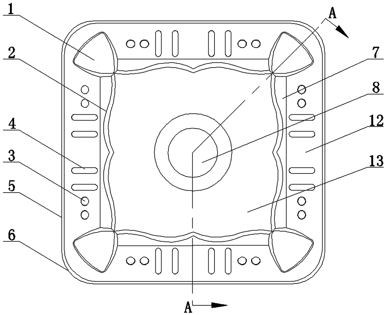
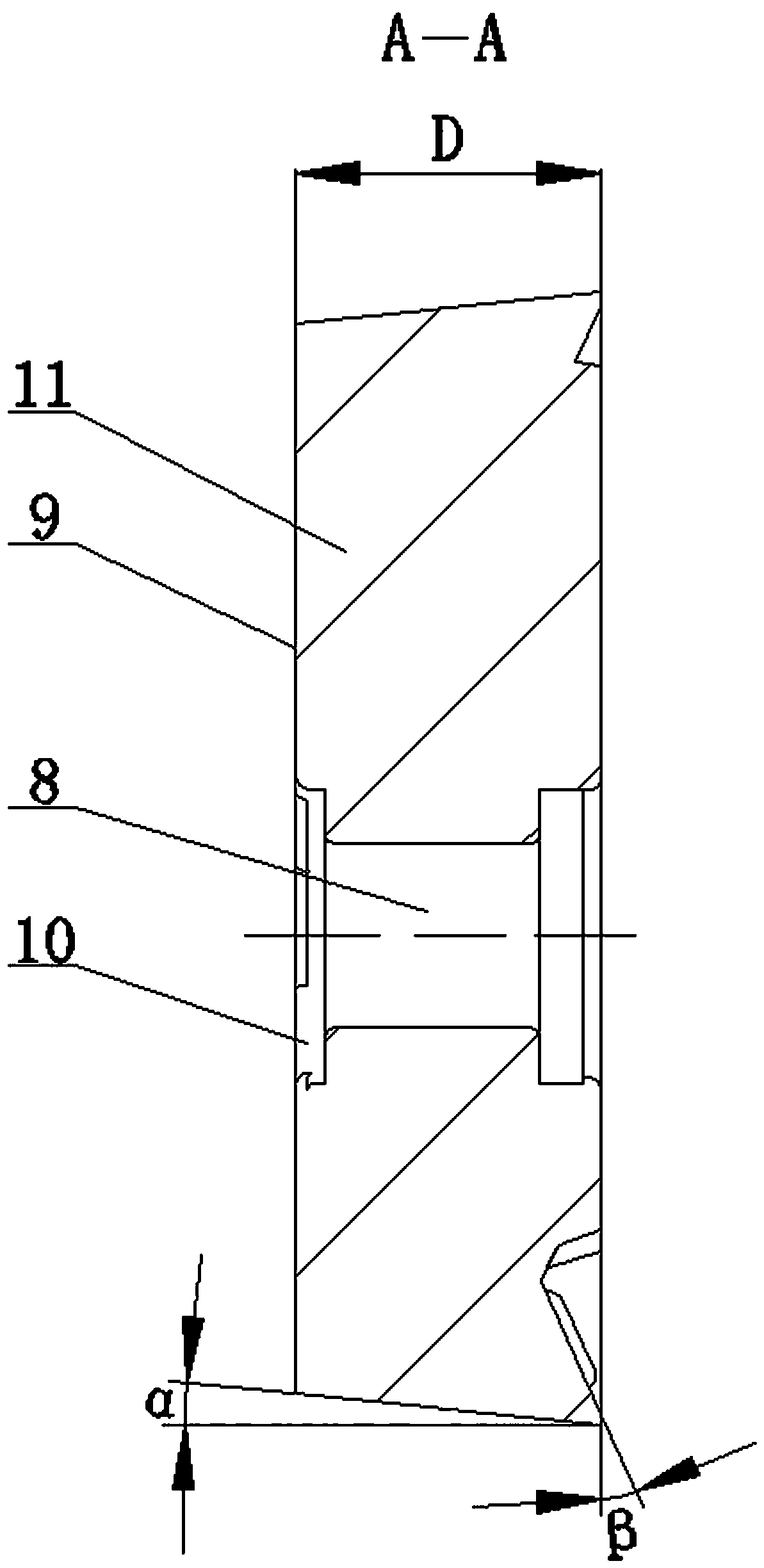
[0024] Specific implementation mode one: as figure 1 and figure 2 As shown, a compound insert for turning and milling with waveform chip guide for heavy-duty cutting, the shape of the insert 11 is a positive quadrangular truncated shape, and the four straight outer edges of the rake face 12 of the insert 11 are all processed with negative chamfering cutting edges 5 , the rake face 12 of the blade 11 is respectively provided with a triangular reinforcing protrusion 1 with a slope near the four tool tips, and the rake face 12 of the blade 11 is respectively provided near the four negative chamfer cutting edges 5 There are a plurality of strip-shaped protrusions 4 and a plurality of spherical protrusions 3, a square boss 13 is provided in the middle area of ​​the rake face 12 of the blade 11, and a fastening screw is arranged on the geometric center of the square boss 13 The four sides of the hole 8 and the square boss 13 are wave-shaped chip guide surfaces 2 with a slope, and ...

specific Embodiment approach 2

[0027] Specific implementation mode two: as figure 1 As shown in the specific embodiment 1, a compound insert for heavy-duty cutting with wave-shaped chip guide turning and milling, the rake face 12 of the insert 11 is provided with a plurality of strips near the four negative chamfer cutting edges 5 The shape protrusion 4 and the plurality of spherical protrusions 3 are arranged symmetrically with respect to the cross center line of the blade 11 respectively.

specific Embodiment approach 3

[0028] Specific implementation mode three: as figure 1 As shown in the specific embodiment 1 or 2, a compound insert for heavy-duty cutting with wave-shaped chip guide turning and milling, the four cutting edges of the cutting edge 11 are respectively provided with a cutting edge arc transition edge 6 .


PUM


Abstract

The invention discloses a heavy cutting waveform guide chip turning and milling compound blade, belongs to the technical field of cutters for heavy cutting, and aims to solve the problems of bad cutter failure, short life and low working efficiency caused by difficult cutter chip breaking, weak heat dissipation and low strength in heavy turning and milling process. The blade takes the shape of a regular four-edge table; negative chamfering cutting edges are respectively machined on the outer edges of four straight lines of the front cutter surface of the blade; triangular reinforced projections with slopes on one side surfaces are respectively arranged on the parts, near four cutter points, of the front cutter surface of the blade; the parts, near the four chamfering cutting edges, of the front cutter surface of the blade respectively provided with multiple strip-shaped projections and multiple spherical projections; a square boss is arranged in the middle area of the front cutter surface of the blade, and is provided with a fastening screw hole in the geometric center; a chip holding groove is defined by the four side surfaces of the square boss and the front cutter surface; and the four side surfaces of the square boss are all waveform chip guide surfaces with slopes. The heavy cutting waveform guide chip turning and milling compound blade is specifically suitable for machining of water chamber seals.

Description

technical field [0001] The invention relates to a heavy-duty turning and milling compound blade, which belongs to the technical field of cutting tools for heavy-duty cutting. Background technique [0002] Nuclear power nuclear island AP1000 evaporator water chamber head (hereinafter referred to as water chamber head) is the most advanced and most difficult part of the third-generation nuclear power plant equipment in the world today, and is the key equipment in the pressurized water reactor nuclear power plant. Large in size and heavy in weight, the purity and density of the material and various physical, chemical and mechanical performance indicators are very high. It is a high-tech product that integrates materials, smelting, forging, heat treatment, flaw detection and measurement. [0003] The material of the water chamber head is high-strength low-alloy 508III steel, which has high plasticity and good high-temperature mechanical properties. Its main processing methods ar...

Claims


Application Information

Patent Timeline
Patent Type & Authority Patents(China)
IPC IPC(8): B23B27/22B23C5/02
CPCB23B27/22B23B2200/08B23B2200/28B23B2200/32B23B2200/321B23C5/02B23C2200/08B23C2200/28B23C2200/32B23C2200/323
Inventor 程耀楠王超贾炜坤聂婉莹关睿
Owner HARBIN UNIV OF SCI & TECH
Why Eureka
Try Eureka