Shortwave Vertical Antenna and Its Supporting Device

A support device and vertical antenna technology, applied in the direction of antenna support/installation device, antenna, loop antenna, etc., can solve the problems of reducing antenna gain and efficiency, and achieve increased gain, increased winding length, and increased effective electrical length Effect

Active Publication Date: 2019-04-09
大唐联诚信息系统技术有限公司
View PDF2 Cites 0 Cited by
  • Summary
  • Abstract
  • Description
  • Claims
  • Application Information

AI Technical Summary

Problems solved by technology

In the frequency range of 3-30MHz, the impedance of the antenna changes sharply with the change of frequency. In order to match the transceiver, an antenna tuner is provided between the antenna and the transceiver to match the impedance of the transceiver. , but there are resistive devices inside the antenna tuner, which will further reduce the efficiency and reduce the gain of the antenna

Method used


Image

  • Shortwave Vertical Antenna and Its Supporting Device
  • Shortwave Vertical Antenna and Its Supporting Device

Examples


Embodiment Construction

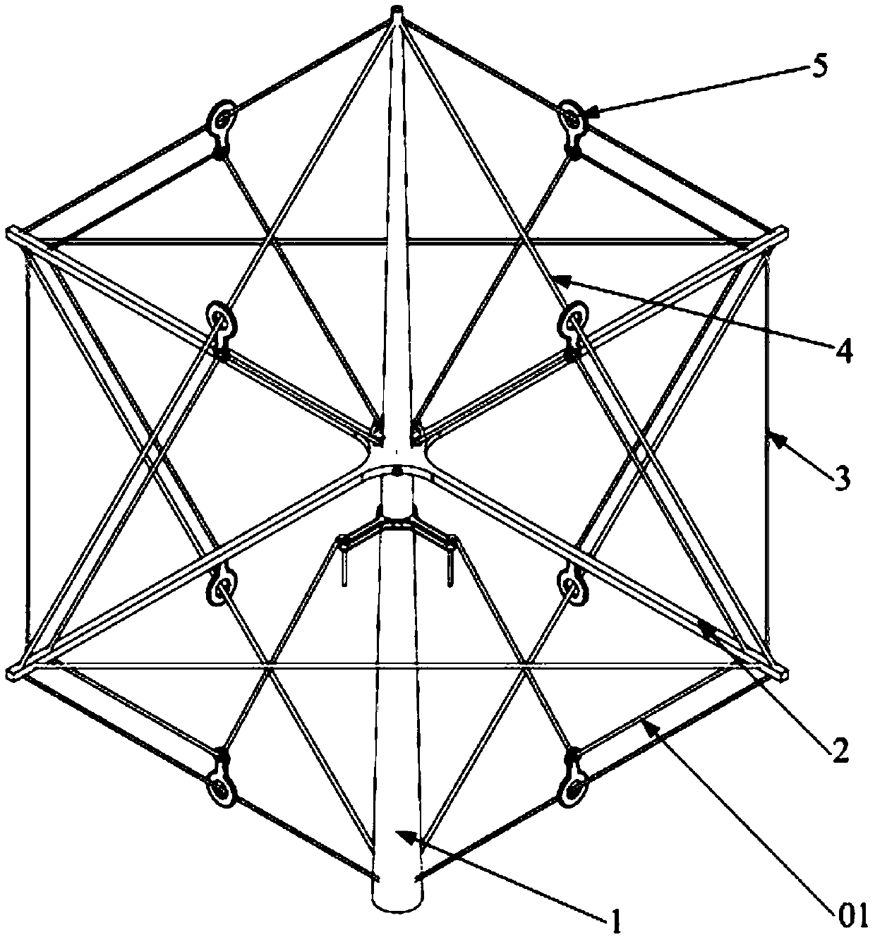
[0026] The embodiment of the present invention provides a winding method for a short-wave vertical antenna, which can realize the resonance of the antenna in the 3-30 MHz short-wave frequency band without increasing the height of the antenna, and at the same time increase the gain of the antenna.

[0027] In order to make the purpose, technical solutions and advantages of the embodiments of the present invention clearer, the technical solutions in the embodiments of the present invention will be clearly and completely described below in conjunction with the drawings in the embodiments of the present invention. Obviously, the described embodiments It is a part of embodiments of the present invention, but not all embodiments. Based on the embodiments of the present invention, all other embodiments obtained by persons of ordinary skill in the art without making creative efforts belong to the protection scope of the present invention.

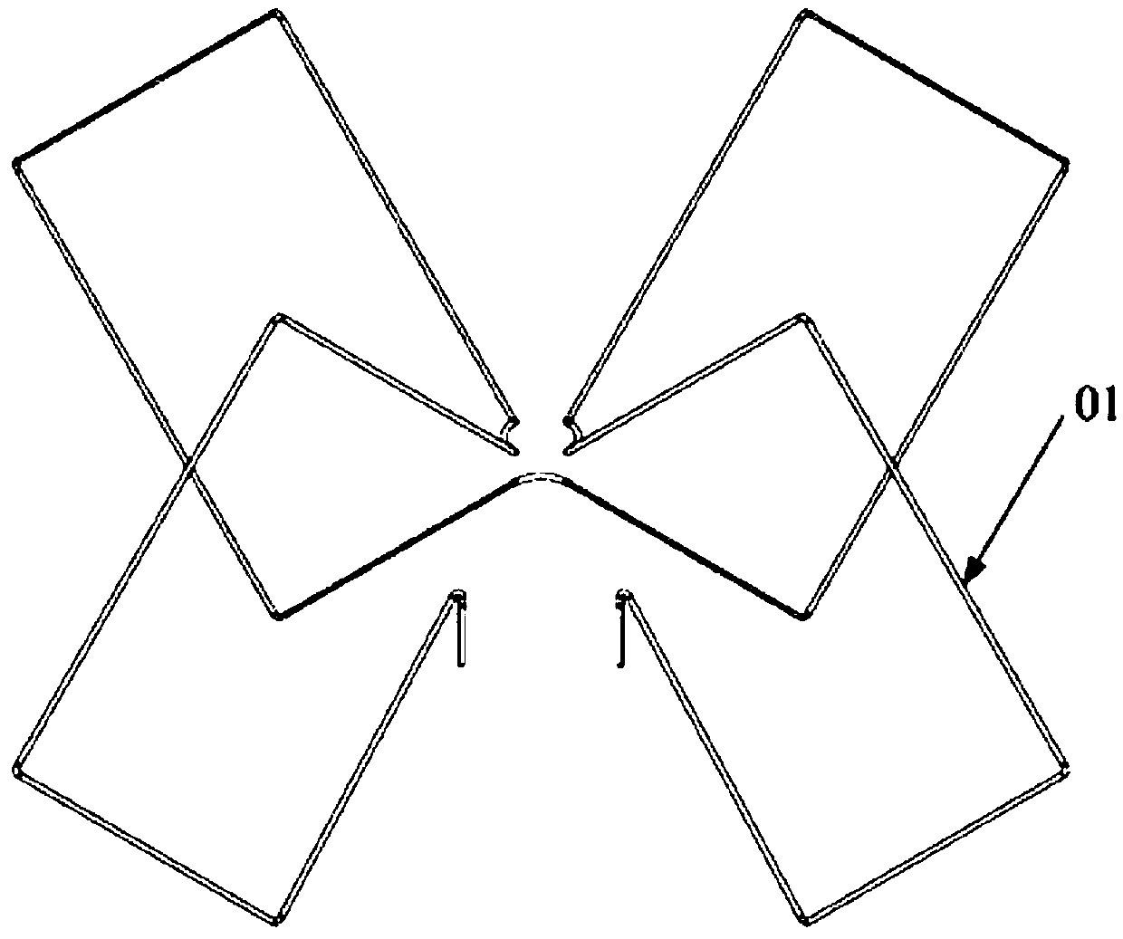
[0028] The winding method of the short-wave ...


PUM


Abstract

The invention provides a winding method of a short-wave vertical antenna. The winding method comprises: a plurality of annular wire rings are wound successively along the top of a vertical rod at the top of an antenna, wherein the annular wire rings are distributed along the peripheral direction of the vertical rod. On the premise that the axial length of the antenna along the vertical rod, that is, the antenna height, does not increase, the winding length of the antenna is increased by using the multiple annular wire rings wound at the top of the antenna and thus the effective electrical length of the antenna element is increased, so that the antenna can realize resonance at a low frequency and the antenna gain is also improved. In addition, the invention also provides a short-wave vertical antenna and a supporting device thereof. Therefore, on the premise that the axial length of the antenna along the vertical rod, that is, the antenna height, does not increase, the winding length of the antenna is increased by using the multiple annular wire rings wound at the top of the antenna and thus the effective electrical length of the antenna element is increased, so that the antenna can carry out resonance at the short-wave frequency band of 3 to 30MHz and the antenna gain also can be improved.

Description

technical field [0001] The invention relates to the technical field of antennas, and more specifically, to a short-wave vertical antenna and a supporting device thereof. Background technique [0002] Due to the limited space on the ship, it is impossible to install dipole antennas, Yagi antennas and logarithmic periodic antennas with large footprints that are often used on the ground. Only vertical antennas with small footprints can be installed. According to the antenna theory, when the length of the vertical antenna is equal to 1 / 4 wavelength of the corresponding frequency, the antenna is in a resonant state, and the characteristic impedance of the antenna is purely resistive, with an impedance of 50Ω. The antenna in this state completely matches the impedance of the transceiver, and the gain of the antenna is the largest and the efficiency is the highest. To require the antenna to be in a resonant state, the length of the antenna must be adjusted so that it is at 1 / 4 wav...

Claims


Application Information

Patent Timeline
Patent Type & Authority Patents(China)
IPC IPC(8): H01Q7/00H01Q1/36H01Q1/12
CPCH01Q1/12H01Q1/36H01Q7/00
Inventor 谢子阳孙剑飞曹晏波
Owner 大唐联诚信息系统技术有限公司
Why Eureka
Try Eureka