
Broadside antenna

An edge-emitting antenna and dielectric substrate technology, which is applied in the field of wide-beam low-profile edge-emitting antennas, can solve the problems of high antenna unit profile, low radiation efficiency, complex structure, etc., and achieves compact antenna structure, high radiation efficiency, and easy manufacturing and processing. Effect

Active Publication Date: 2016-12-21
CHONGQING UNIV +1
View PDF8 Cites 0 Cited by
  • Summary
  • Abstract
  • Description
  • Claims
  • Application Information

AI Technical Summary

Problems solved by technology

[0004] The purpose of the present disclosure is to provide a side-fire antenna, which is used to solve the problems of the existing antenna unit with high profile, complex structure and low radiation efficiency

Method used


Image

  • Broadside antenna
  • Broadside antenna
  • Broadside antenna

Examples


Embodiment Construction

[0036] Reference will now be made in detail to the exemplary embodiments, examples of which are illustrated in the accompanying drawings. When the following description refers to the accompanying drawings, the same numerals in different drawings refer to the same or similar elements unless otherwise indicated. The implementations described in the following exemplary examples do not represent all implementations consistent with the present disclosure. Rather, they are merely examples of apparatuses and methods consistent with aspects of the present disclosure as recited in the appended claims.

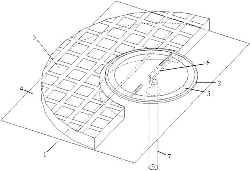
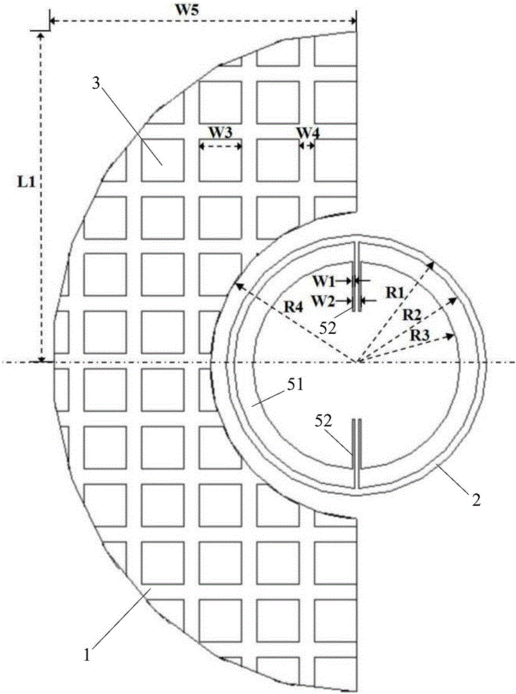
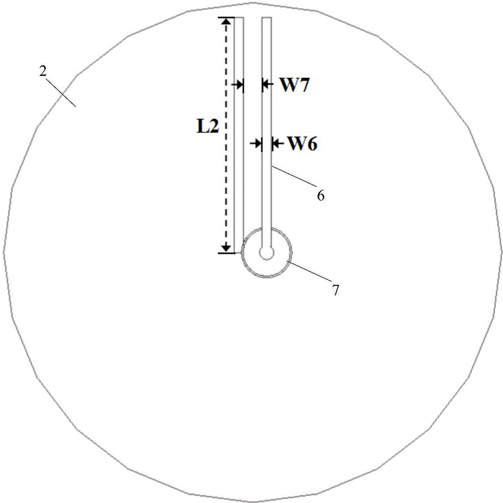
[0037] figure 1 is a schematic structural diagram of a side-fire antenna shown according to an exemplary embodiment, as shown in figure 1 As shown, the side-fire antenna includes:

[0038] The first dielectric substrate 1 is provided with a gap and includes opposite first and second surfaces;

[0039] Metal patches 3 are arranged and attached to the first surface;

[0040] The grou...


PUM


Abstract

The invention discloses a broadside antenna. The broadside antenna comprises a first dielectric substrate, metal patches, a grounding plate, a second dielectric substrate, a magnetic dipole, an excitation source and a coaxial cable, wherein the first dielectric substrate is provided with a gap and comprises a first surface and a second surface which are opposite to each other, the metal patches are arranged in contact with the first surface, a groove hole is formed in the grounding plate and is in contact with the second surface, the second dielectric substrate is arranged in parallel to the grounding plate and comprises a third surface and a fourth surface which are opposite to each other, a partial region of the projection of the second dielectric substrate on the grounding plate is arranged in the gap, the magnetic dipole is in contact with the third surface, the excitation source is in contact with the fourth surface, and the coaxial cable is arranged in the groove hole in a penetrating way and is connected with the excitation source. The broadside antenna disclosed by the invention has the characteristics of low profile and favorable end emission radiation; and by loading an EBG (Electromagnetic Band Gap) technology, the broadside antenna has favorable side emission radiation characteristic and extremely wide beam width, and the problems of relatively high profile, relatively low radiation efficiency and the like of an existing antenna are solved.

Description

technical field [0001] The present disclosure relates to the field of antennas, in particular to a wide-beam low-profile edge-fire antenna applied to a phased array. Background technique [0002] A phased array is an antenna array composed of multiple antenna elements that can scan beams by controlling the relative phase between the elements. This array has the advantages of high gain, low sidelobe, high power, etc., and can be widely used in radar, aerospace, remote sensing and telemetry and other fields. The aircraft is generally equipped with a planar phased array antenna, which is composed of ordinary microstrip antenna units, and is an important device for the aircraft to perceive the surrounding environment. However, due to the limitation of the antenna unit, the scanning range of the planar phased array antenna is very narrow, which greatly limits the spatial search area of ​​the phased array. [0003] In order to break through this limitation, a large-angle scannin...

Claims


Application Information

Patent Timeline
Patent Type & Authority Applications(China)
IPC IPC(8): H01Q1/38H01Q1/50H01Q1/48
CPCH01Q1/38H01Q1/48H01Q1/50
Inventor 唐明春周博雅陈世勇理查德·齐奥尔科夫斯基肖磊
Owner CHONGQING UNIV
Learn More