
Telescopic movable bridge and using method

A telescoping, abutment technology applied to open bridges. It can solve problems such as bridge opening restrictions, traffic impact, poor adaptability to water level changes, etc., and achieve the effect of simplifying the structure and ensuring safety

Inactive Publication Date: 2016-12-21
CHINA HARZONE IND CORP
View PDF6 Cites 9 Cited by
  • Summary
  • Abstract
  • Description
  • Claims
  • Application Information

AI Technical Summary

Problems solved by technology

The existing horizontal opening bridges generally use floating horizontal opening bridges. This type of opening bridge is greatly affected by the water level, and the elevation of the bridge deck will change, which will have a certain impact on traffic.
The vertical lifting open bridge needs to build lifting devices on the abutments on both sides of the bridge, and generally limits the height of navigation, and has poor adaptability to water level changes; the bridge main body of the vertically rotating open bridge rotates around a fixed axis in the air, and uses hydraulic cylinders to shrink Or elongate to drive the opening and closing of the bridge. In the open state, the bridge hangs at a certain angle in the air to meet the requirements of the ship's navigation clearance. In bad weather, the opening of the bridge will be restricted; moreover, there are common problems in the vertical lifting and vertical opening opening bridges: when the bridge is open, ships need to pass under the opening bridge, which has certain safety hazards

Method used


Image

  • Telescopic movable bridge and using method
  • Telescopic movable bridge and using method
  • Telescopic movable bridge and using method

Examples


Embodiment 1

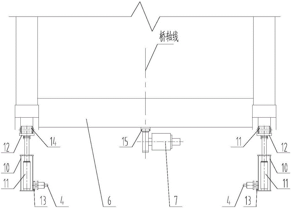
[0023] Embodiment 1, see attached figure 1 , a telescopic opening bridge, which includes: left abutment 1, guide beam slideway 2, guide beam 3, guide beam propulsion mechanism 4, fixed slideway 5, bridge span 6, push bridge mechanism 7, right abutment 8 , hydraulic system, electrical system;

[0024] See attached figure 2 , 3 , two sets of fixed slideways 5 are symmetrically arranged on the upper surface of the left abutment 1 along the bridge axis; the bridge pushing mechanism 7 is installed on the front end of the left abutment 1 along the bridge axis; two sets of guide beam slideways 2 are symmetrically installed on the fixed Inside the left abutment 1 below the slideway 5; two sets of guide beams 3 are symmetrically installed in the guide beam slideways 2 along the bridge axis, and two sets of guide beam propulsion mechanisms 4 are respectively fixedly installed on the front ends of the two sets of guide beam slideways 2; Two sets of guide beam bearings 9 are arranged ...

Embodiment 2

[0028] Embodiment 2: see attached Figure 4-8 , a telescopic opening bridge using method, it uses a kind of telescopic opening bridge as described in embodiment 1, comprises the following steps:

[0029] A. The bridge opens

[0030] The guide beam 3 is driven by the guide beam propulsion mechanism 4 to reach the guide beam support 9 of the right abutment 8 and is in place, and the lifting cylinder 11 stretches out to lift the lifting slideway 12 and the bridge span 6. At this time, the lifting slideway 12 and the fixed The slideway 5 is located on the same plane, and the second pin gear of the push bridge mechanism 7 is stretched out to mesh with the second pin tooth 15, and the drive bridge span 6 is moved from the lifting slideway 12 to the fixed slideway 5, and the lifting cylinder 11 is retracted. Put the lifting slideway 12 back into place, and the guide beam propulsion mechanism 4 drives the guide beam 3 to retract into the guide beam slideway 2 and put it in place, com...


PUM


Abstract

The invention belongs to the technical field of bridges, and relates to a telescopic movable bridge and a using method, in particular to a movable bridge. According to the technical scheme, the telescopic movable bridge comprises a left bridge abutment, guide beam slideways, guide beams, guide beam propelling mechanisms, fixed slideways, a bridge span, a bridge pushing mechanism, a right bridge abutment, a hydraulic system and an electrical system. In the opening and closing processes of the bridge, the guide beams extend firstly to serve as a support of the bridge span, so that the structure of the bridge span is greatly simplified, and the stability and reliability in the opening and closing processes of the bridge are improved. When the bridge is in the opened state, the bridge span is located on the fixed slideways on the upper surfaces of the bridge abutments, potential safety hazards to ships passing through a riverway do not exist, and the safety of the bridge and the ships is ensured.

Description

technical field [0001] The invention belongs to the technical field of bridges, in particular to an open bridge. Background technique [0002] At present, the opening methods of the opening bridge include horizontal rotation opening, vertical lifting, vertical rotation opening and so on. Existing horizontal-rotating opening bridges generally adopt floating horizontal-rotating opening. This type of opening bridge is greatly affected by the water level, and the elevation of the bridge deck will change, which will have a certain impact on traffic. The vertical lifting open bridge needs to build lifting devices on the abutments on both sides of the bridge, and generally limits the height of navigation, and has poor adaptability to water level changes; the bridge main body of the vertically rotating open bridge rotates around a fixed axis in the air, and uses hydraulic cylinders to shrink Or elongate to drive the opening and closing of the bridge. In the open state, the bridge h...

Claims


Application Information

Patent Timeline
IPC IPC(8): E01D15/12
CPCE01D15/124
Inventor 杨志平易良华方俊
Owner CHINA HARZONE IND CORP
Learn More