
Special grinding machine for sucker rod

A special grinding machine and sucker rod technology, applied in the direction of grinding machine, abrasive belt grinder, grinding bed, etc., can solve the economic loss, can not solve the problems of water leakage, oil leakage, gas leakage, affecting the civilized production of oil fields, etc. Thick and thin effect

Active Publication Date: 2016-12-21
崔永金
View PDF7 Cites 6 Cited by
  • Summary
  • Abstract
  • Description
  • Claims
  • Application Information

AI Technical Summary

Problems solved by technology

Not only directly brought economic losses, but also affected the civilized production of oil fields
The traditional solution, when replacing the packing can not solve the problem of water leakage, oil leakage, air leakage, it is necessary to replace the new sucker rod
To replace a new sucker rod, the cost of shutting down the oil well is not including the cost of more than 9,000 yuan, and the loss caused by the shutting down of the oil well is tens of thousands of yuan.

Method used


Image

  • Special grinding machine for sucker rod
  • Special grinding machine for sucker rod
  • Special grinding machine for sucker rod

Examples


Embodiment Construction

[0010] Below in conjunction with accompanying drawing and embodiment the present invention is further described

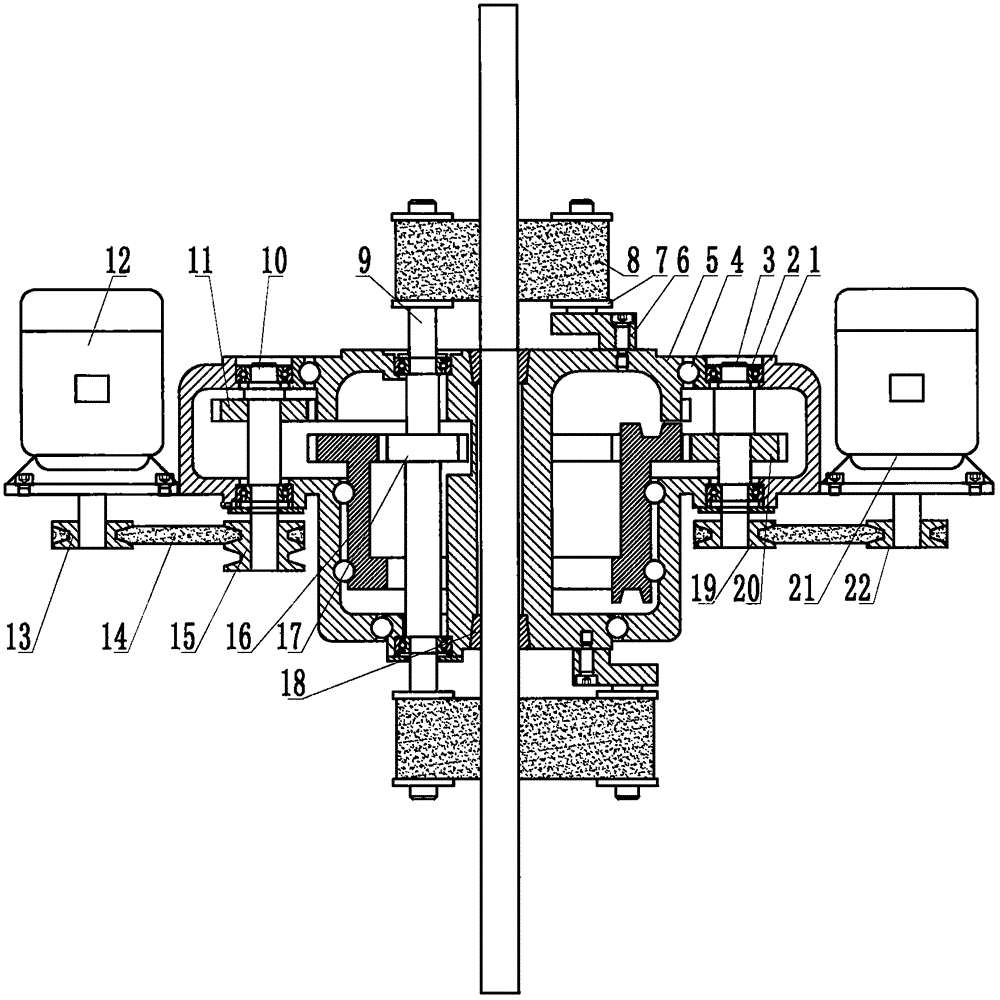
[0011] Such as Figure 1-Figure 3 As shown, the special grinding machine for sucker rods has the following structure: the shell 1 is a hollow circular table shell made of metal, and the inner circle of the shell 1 is provided with arc-shaped chutes for installing balls on the top, middle and bottom respectively. The outer upper end of the casing 1 is provided with a wire rope hook 32, and the upper end of the outer casing 1 is provided with an opening 2 34; the outer casing 1 is respectively equipped with a vertical motor 1 12, a vertical motor 2 21 and a worm gear reducer 25, and the vertical motor One 12 lower end is equipped with belt pulley one 13, vertical motor two 21 lower ends are equipped with belt pulley three 22; The position corresponding to the vertical motor 2 21 is provided with a shaft 3, the upper and lower ends of the shaft 3 are slidingly connec...


PUM


Abstract

The invention discloses a special grinding machine for a sucker rod, and belongs to the technical field of pumping unit equipment of the petroleum machinery. A shell is a hollow circular-platform shell made of shell. Arc sliding grooves provided with balls are formed in the upper portion, the middle portion and the lower portion of an inner sphere of the shell. A steel wire rope hook is arranged at the upper end of the outer side of the shell. A second opening is formed in the upper end of the outer side of the shell. A first vertical motor, a second vertical motor and a worm and gear speed reducer are arranged on the outer side of the shell. A first belt wheel is arranged at the lower end of the first vertical motor, and a third belt wheel is arranged at the lower end of the second vertical motor. A steel wire rope roller is arranged at one shaft end of the worm and gear speed reducer. A revolution gear shaft is a cavity, a first opening is formed in the upper end, arc sliding grooves provided with balls are formed in the outer ends of the upper side and the lower side, and the revolution gear shaft is in sliding connection with the shell through the balls. An outer gear ring is arranged in the middle of the revolution gear shaft. Shaft holes for installing an eccentric block and a power output shaft are formed in the upper end of the revolution gear shaft, the eccentric block is arranged at the upper end of the revolution gear shaft through an eccentric block shaft, and a tensioning wheel is arranged at the upper end of the eccentric block.

Description

technical field [0001] The invention relates to a special grinder for sucker rods, belonging to the technical field of oil pumping unit equipment for petroleum machinery. Background technique [0002] Existing self-priming pumping unit, the packing inside the packing box of its wellhead part is closely combined with the sucker rod, to seal the high-pressure water, oil and gas in the wellhead inside. Due to the non-stop reciprocating motion of the sucker rod, the friction between the packing and the sucker rod makes the sucker rod wear continuously, coupled with the erosion of the sucker rod by wind, sand and chemical substances, the surface of the sucker rod changes The thickness is uneven, and there are spots of corrosion. At the same time, due to changes in the oil layer, it is necessary to adjust the parameters of the sucker rod, that is, to adjust the depth of the sucker rod to pump oil and gas from different oil layers. After the adjusted sucker rod is raised, two size...

Claims


Application Information

Patent Timeline
Patent Type & Authority Applications(China)
IPC IPC(8): B24B21/00B24B21/02B24B21/18B24B41/02B24B41/06B24B47/04
CPCB24B21/008B24B21/02B24B21/18B24B41/02B24B41/067B24B47/04
Inventor 张坚崔桂霞
Owner 崔永金
Learn More