Turbine arrangement

A turbine and turbine technology, applied in the combustion method, combustion chamber, combustion control and other directions, can solve the problems of limiting the load range and reducing the combustion temperature, and achieve the effect of reducing the risk

Inactive Publication Date: 2016-12-14
SIEMENS AG
View PDF6 Cites 2 Cited by
  • Summary
  • Abstract
  • Description
  • Claims
  • Application Information

AI Technical Summary

Problems solved by technology

As a result, the combustion temperature associated with CO emissions also decreases, which results in stronger CO emissions
If the CO emissions correspond to the legal limit values, then it should be ensured that the combustion temperature does not fall below the minimum value, but this significantly limits the usable part load range of the turbine arrangement

Method used


Image

  • Turbine arrangement
  • Turbine arrangement
  • Turbine arrangement

Examples


Embodiment Construction

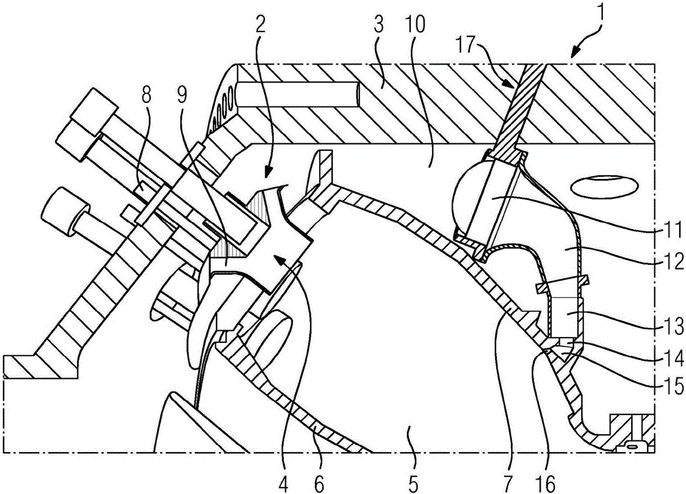
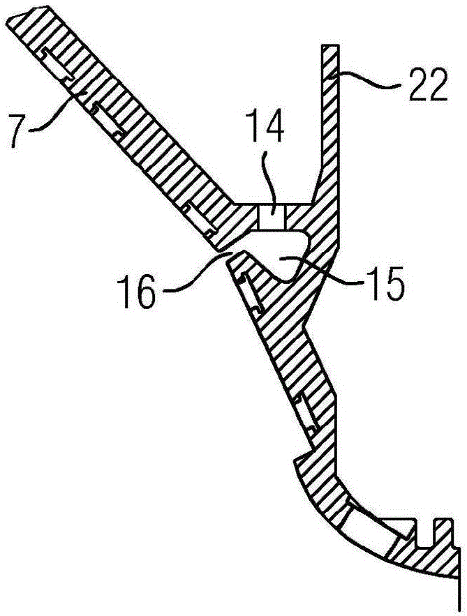
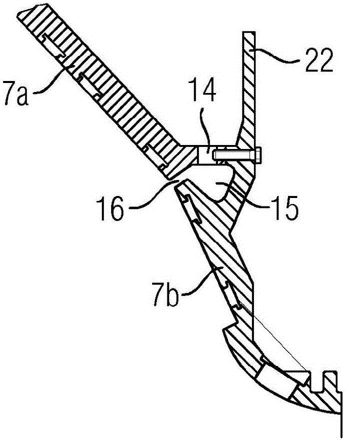
[0040] Figures 1 to 8 A partial area of ​​a turbine arrangement 1 according to a first embodiment of the invention is shown. The turbo device 1 comprises a compressor (not further shown), at least one combustion device 2 and a turbine (also not further shown), which is arranged in a machine housing 3 . The machine housing 3 is assembled from a number of machine housing parts, but this will not be discussed in more detail below.

[0041] The combustion device 2 has several annular burners 4 and opens into a stone-paved combustion chamber 5 formed by a combustion chamber sleeve 6 and a housing 7 connected to the combustion chamber sleeve 6 . Each burner 4 includes a fuel delivery pipe 8 and an air outlet 9, and the fuel delivery pipe 8 extends through the mechanical housing 3, so that the burner 4 can deliver fuel through a fuel delivery device arranged outside the mechanical housing 3, through The air supply port 9 introduces the ambient air compressed by the compressor into ...


PUM


Abstract

The invention relates to a turbine arrangement (1; 30; 45; 47) with a compressor, at least one burner arrangement (2; 31; 48) comprising multiple burners (4) and a combustion chamber (5; 34; 51), and a turbine (49), wherein the compressor, the at least one burner arrangement (2; 31; 48) and the turbine (49) are fluidically connected to one another such that, during proper operation, air compressed by the compressor is guided through the burners (4) and is mixed with fuel, whereupon the fuel-air mixture produced is burnt in the combustion chamber (5; 34; 51) and the combustion gases are fed to the turbine (49), characterized in that there is provided a bypass device which is designed such that part of the air compressed by the compressor can be guided, as a bypass flow, past the burners (4) into the region of the outlet end of the combustion chamber (5; 34; 51).

Description

technical field [0001] The invention relates to a turbo device having a compressor, at least one combustion device comprising a plurality of burners and a combustion chamber and a turbine, wherein the compressor, the at least one combustion device and the turbine are fluidically connected to one another , so that during normal operation air compressed by the compressor is directed through the combustor and mixed with fuel whereby the resulting fuel-air mixture is combusted within the combustion chamber and the combustion gases are delivered to the turbine. Background technique [0002] Turbine arrangements of the aforementioned kind are known in different technical solutions from the prior art. During operation, ambient air is compressed and delivered to a plurality of burners of at least one combustion device by using a compressor. In these burners compressed air is mixed with fuel and the resulting mixture is then combusted in the combustion chamber by generating combusti...

Claims


Application Information

Patent Timeline
Patent Type & Authority Applications(China)
IPC IPC(8): F23R3/06F23R3/26
CPCF23R3/06F23N2900/05001F23R3/26
Inventor H·布勒多恩M·拉森M·特蒂尔特M·维尔克C·格兰特D·霍尔德A·克卢格
Owner SIEMENS AG
Why Eureka
Try Eureka