


Quick Research
Generate reliable direction feasibility study reports for your R&D in just a few steps.

Technical Q&A
Discover and master advanced knowledge NOW. Basics, ideas, possibilities, all at once.

Find Solutions
As an expert in R&D theories, this can generate solutions to your technical problems instantly.

Evaluate Feasibility
Analyze your overall solution with one click, know your potential R&D risks in advance.

Monitor Landscape
Get weekly tech updates, stay abreast of the latest tech innovations and key insights.
Moulding tool for producing hot-formed components
A technology of thermoforming and forming parts, applied in the direction of manufacturing tools, forming tools, cleaning methods and appliances, etc., can solve unsustainable, expensive and other problems, and achieve the effect of improving sustainability
- Summary
- Abstract
- Description
- Claims
- Application Information
AI Technical Summary
Problems solved by technology
Method used
Image

Examples
Embodiment Construction
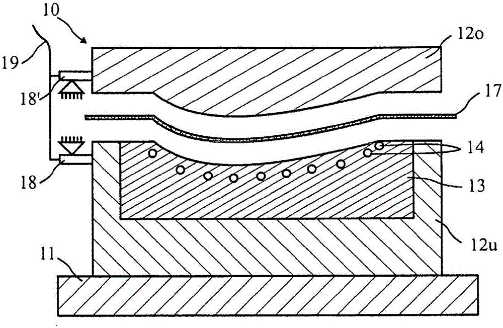
[0025] figure 1 A die 10 is shown, which can be used in a press for thermoforming a sheet metal blank of a sheet metal component 17 . The mold 10 comprises a lower mold half 12 u which rests on the base plate 11 . The lower mold half 12u cooperates with the upper mold half 12o. The mutually facing active surfaces of the upper mold half 12o and the lower mold half 12u are designed correspondingly so that they serve as a die and a punch of a stamping tool. exist figure 1 In the example shown, the upper mold half 12o is designed as a punch and the lower mold half 12u is designed as a die. Without departing from the scope of the present invention, the upper mold half and the lower mold half can be exchanged with respect to their arrangement, so that the upper mold half acts as a die and the lower die half acts as a punch. The upper mold half 12o and the lower mold half 12u are movable relative to each other. figure 1 The shown mold halves 12o, 12u can be moved away from each ...
PUM
 Abstract
Description
Claims
Application Information
 - R&D Engineer
- R&D Manager
- IP Professional
- Industry Leading Data Capabilities
- Powerful AI technology
- Patent DNA Extraction
Browse by: Latest US Patents, China's latest patents, Technical Efficacy Thesaurus, Application Domain, Technology Topic, Popular Technical Reports.
© 2024 PatSnap. All rights reserved.Legal|Privacy policy|Modern Slavery Act Transparency Statement|Sitemap|About US| Contact US: help@patsnap.com