Key structure and electronic equipment
A button and metal plate technology, which is applied in the electronic field, can solve the problems of uneven installation gap, low processing efficiency, and uneven installation, and achieve the effect of reducing manufacturing steps, reducing failures, and reducing connection structures
- Summary
- Abstract
- Description
- Claims
- Application Information
AI Technical Summary
Problems solved by technology
Method used
Image
Examples
Embodiment 1
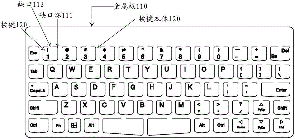
[0032] Such as figure 1 As shown, this embodiment provides a button structure, including: a metal plate 110;
[0033] N gap rings 111 are provided on the metal plate 110; the N is an integer not less than 1; the gap rings 111 are composed of incompletely closed gaps; the unclosed parts of the gap rings 111 are the gaps ring gap 112;
[0034] The metal plate 110 located inside the notch ring 111 forms a key 120, and the metal plate 110 located outside the notch ring 111 is a key body 130;
[0035] The metal plate 110 located at the notch 112 is a cantilever connecting the key 120 and the key body 130 .
[0036] In this embodiment, the metal plate 110 may be a plate made of various metals or metal alloys, and in this embodiment is preferably a metal plate made of an elastic metal plate.
[0037] In this embodiment, the metal plate 110 is provided with one or more gap rings 111 , for example, the gap ring 111 has two gaps correspondingly. Here, the notch of the notch ring 111...
Embodiment 2
[0044] Such as figure 1 As shown, this embodiment provides a button structure, including: a metal plate 110;
[0045] N gap rings 111 are provided on the metal plate 110; the N is an integer not less than 1; the gap rings 111 are composed of incompletely closed gaps; the unclosed parts of the gap rings 111 are the gaps ring gap 112;
[0046] The metal plate 110 located inside the notch ring 111 forms a key 120, and the metal plate 110 located outside the notch ring 111 is a key body 130;
[0047] The metal plate 110 located at the notch 112 is a cantilever connecting the key 120 and the key body 130 .
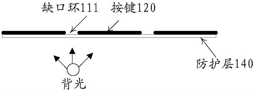
[0048] Such as figure 2 As shown, a protective layer 140 is disposed on the first surface of the metal plate 110 , covering at least the gap corresponding to the gap ring 111 .
[0049] The protective layer can be a waterproof layer and / or a dustproof layer, in short, it can be a protective structure. In this embodiment, the protective layer 140 can cover the entire first...
Embodiment 3
[0052] Such as figure 1 As shown, this embodiment provides a button structure, including: a metal plate 110;
[0053]N gap rings 111 are provided on the metal plate 110; the N is an integer not less than 1; the gap rings 111 are composed of incompletely closed gaps; the unclosed parts of the gap rings 111 are the gaps ring gap 112;
[0054] The metal plate 110 located inside the notch ring 111 forms a key 120, and the metal plate 110 located outside the notch ring 111 is a key body 130;
[0055] The metal plate 110 located at the notch 112 is a cantilever connecting the key 120 and the key body 130 .
[0056] A protective layer 140 is disposed on the first surface of the metal plate 110 , covering at least the gap corresponding to the gap ring 111 .
[0057] The protective layer 140 is a transparent protective layer for allowing light to pass through the first surface of the key 120 to provide backlight for the key 120;
[0058] The second surface of the key 120 is provide...
PUM
 Abstract
Description
Claims
Application Information
 - R&D Engineer
- R&D Manager
- IP Professional
- Industry Leading Data Capabilities
- Powerful AI technology
- Patent DNA Extraction
Browse by: Latest US Patents, China's latest patents, Technical Efficacy Thesaurus, Application Domain, Technology Topic, Popular Technical Reports.
© 2024 PatSnap. All rights reserved.Legal|Privacy policy|Modern Slavery Act Transparency Statement|Sitemap|About US| Contact US: help@patsnap.com


