
Electronic device

A technology of electronic devices and functions, applied in the direction of TV, electrical components, color TV, etc., can solve the problems of camera vibration and affect the quality of photography, and achieve the effect of increasing strength, avoiding poor use and saving costs.

Inactive Publication Date: 2012-09-19
QISDA SUZHOU +1
View PDF4 Cites 4 Cited by
  • Summary
  • Abstract
  • Description
  • Claims
  • Application Information

AI Technical Summary

Problems solved by technology

[0002] Traditional electronic devices use buttons to perform specific functions. Take a camera as an example. When a user wants to take a photo, he must press the button (shutter) to take a photo. However, pressing the button may cause the camera to vibrate, which will affect the quality of the photo.

Method used


Image

  • Electronic device
  • Electronic device
  • Electronic device

Examples


Embodiment Construction

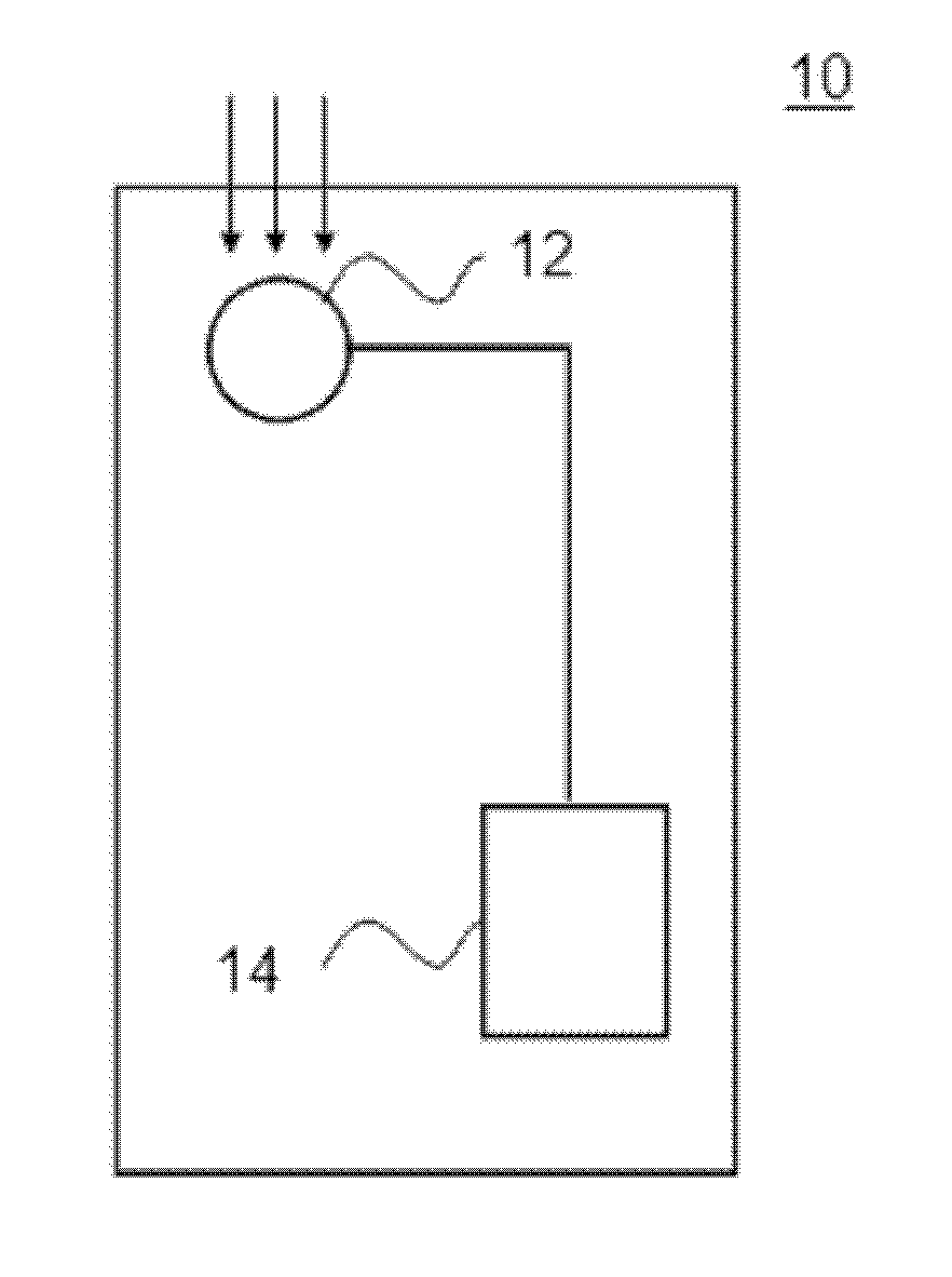
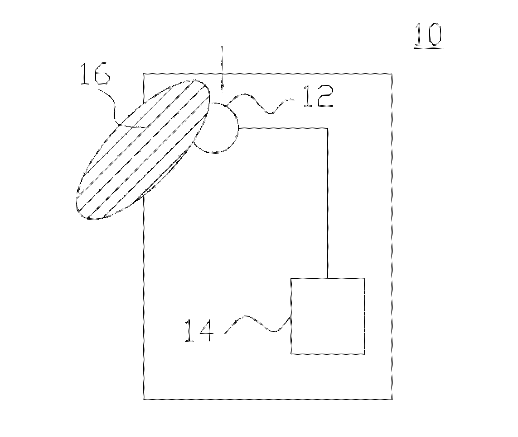
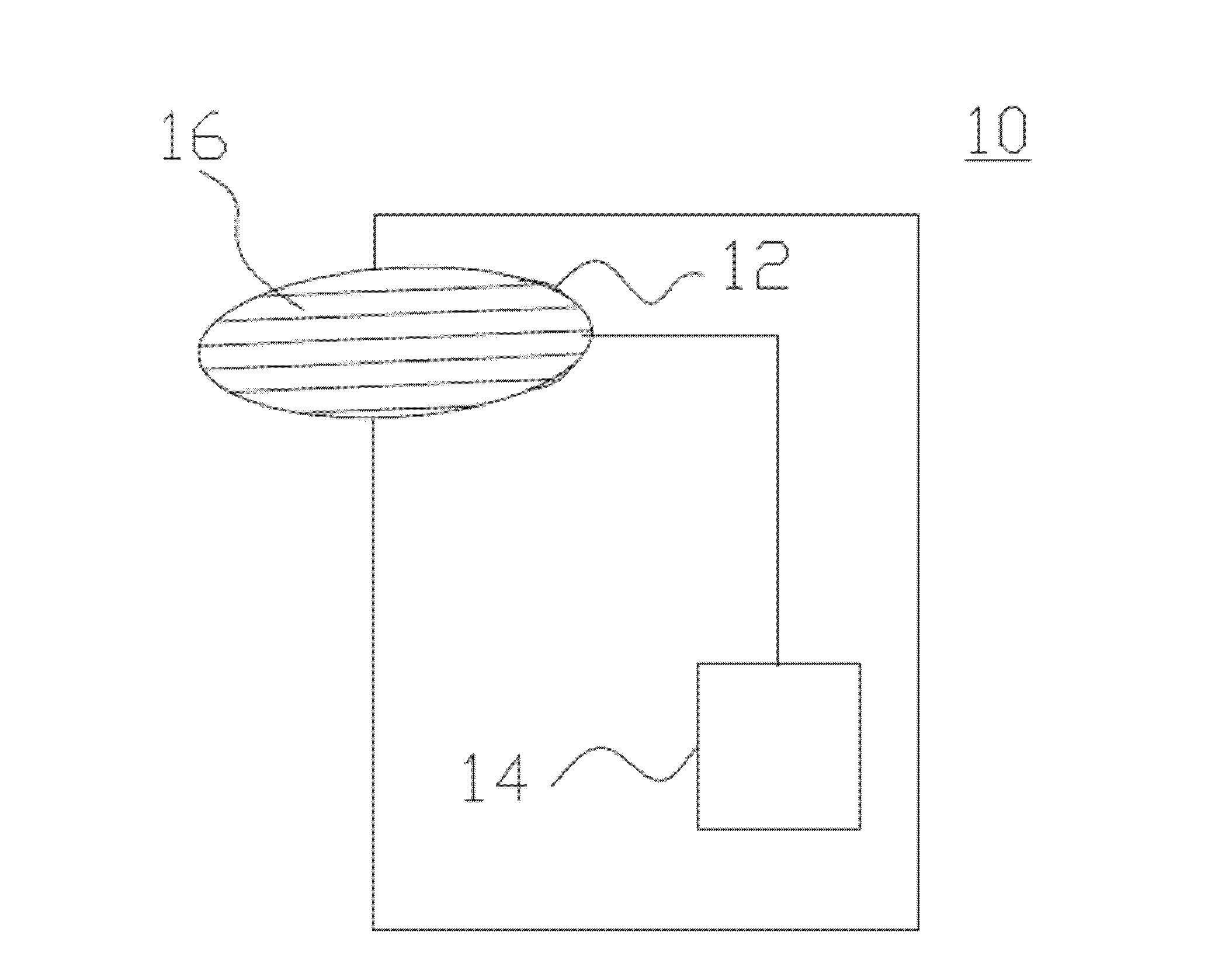
[0018] The main purpose of the present invention is to provide an electronic device that uses a light sensor to detect ambient light brightness. When the light sensor is in the first light-shielding state, the electronic device performs the first function. When the light sensor In the second light-shielding state, the electronic device executes the second function. Various embodiments are provided below for detailed description, and the embodiments are only used as examples for illustration, and are not intended to limit the scope of protection of the present invention.

[0019] First, see figure 1 , figure 1 It is a structural diagram of a preferred embodiment of the present invention; as shown in the figure, the electronic device 10 of the present invention includes a light sensor 12 and a control unit 14 . The control unit 14 controls the electronic device 10 to execute the first function or the second function. In one embodiment, the electronic device 10 can be a camera,...


PUM


Abstract

The invention relates to an electronic device. The electronic device comprises a control unit and a photodetector, wherein the control unit is used for controlling the electronic device to implement a first function or a second function; the photodetector is used for detecting the ambient brightness and is coupled with the control unit; and when the photodetector is in the first shading state, the electronic device implements the first function; and when the photodetector is in the second shading state, the electronic device implements the second function. The electronic device has the following advantages that: as the electronic device implements different functions according to different states of the photodetector, the electronic device self is not directly contacted with operations of implementing some functions, thus avoiding poor use of the electronic device caused by vibration generated by pressing keys and simplifying the structure of the electronic device.

Description

technical field [0001] The present invention relates to an electronic device, in particular, the present invention relates to an electronic device with a light sensor, and uses the light sensor to perform multiple functions of the electronic device. Background technique [0002] Traditional electronic devices use buttons to perform specific functions. Taking a camera as an example, when a user wants to take a photo, he must press a button (shutter) to take a photo. However, pressing may cause the camera to vibrate, thereby affecting the quality of the photo. Contents of the invention [0003] One of the objectives of the present invention is to provide an electronic device that performs different functions correspondingly according to the different states of the light sensor, so that the operation of performing some functions does not directly contact the electronic device itself, thereby avoiding electronic damage caused by vibration caused by pressing the button. The phe...

Claims


Application Information

Patent Timeline
Patent Type & Authority Applications(China)
IPC IPC(8): H04N5/232
Inventor 郭泰佑
Owner QISDA SUZHOU
Learn More