Heat energy power system comprehensively utilizing waste heat of acting pump

A power system and work technology, applied in the field of energy utilization equipment, can solve the problems of unstable medium pressure, low mechanical energy conversion efficiency, and easy deterioration of working fluid, so as to improve gasification efficiency and condensation efficiency, improve thermal energy conversion efficiency, avoid Incomplete condensation effect

Inactive Publication Date: 2016-12-14
郭远军
View PDF0 Cites 0 Cited by
  • Summary
  • Abstract
  • Description
  • Claims
  • Application Information

AI Technical Summary

Problems solved by technology

[0005] Existing thermal energy utilization equipment that uses gas expansion to do work, under ideal conditions, has the highest rate of thermal energy conversion, which is the Carnot cycle efficiency, that is, 1-T 0 / T 1 , where T 0 is the temperature of the cold source, T 1 It is a high-temperature heat source; but in the actual work process of thermal equipment, on the one hand, due to the gasification process of the circulating working fluid in the gasification device, the actual temperature of its gasification expansion has a large temperature difference with the temperature of the high-temperature heat source, and the actual temperature is lower than the temperature of the high-temperature heat source , whose theoretical T 1 On the other hand, because the actual condensation temperature of the circulating working fluid in the condensing device is higher than the temperature of the low-temperature cold source, its theoretical T 0 increase, leading to a decrease in the maximum efficiency of thermal energy; in addition, due to the low absorption rate of the turbine for gas expansion work, its mechanical energy conversion efficiency is low; in addition, the circulating working fluid is prone to impurities, and the circulating working medium consumes a lot of energy
[0006] The specific problems caused by the above-mentioned deviations in existing thermal energy equipment include: 1. The thermal conductivity of the gasification device is poor, and the temperature requirements for high-temperature heat sources are high; 2. The pressure of the gasification device is unstable, and the temperature required for gasification is unstable , when the temperature required for gasification is greater than the temperature of the heat source, the medium cannot be vaporized; when the temperature required for gasification is lower than the temperature of the heat source, the gasification expansion temperature is low, the heat absorption is small, and the net work is small; 3. Condensing device The pressure of the internal medium is unstable, and the temperature required for condensation is unstable. When the temperature required for condensation is lower than the temperature of the cold source, condensation cannot be achieved. When the temperature required for condensation is greater than the temperature of the cold source, the temperature after condensation is too low; 4. Condensation device The internal condensation is not complete, and the gas-liquid mixed state is prone to appear, resulting in a relatively small gasification and expansion volume of the working fluid in the gasification device; 5. The existing turbine has a relatively small torque, large volume leakage, and low efficiency; 6. The thermal energy conversion efficiency of existing thermal energy equipment is low, and the thermal energy conversion efficiency is generally 10% to 30%; 7. The working medium is easy to deteriorate or appear impurities

Method used


Image

  • Heat energy power system comprehensively utilizing waste heat of acting pump
  • Heat energy power system comprehensively utilizing waste heat of acting pump
  • Heat energy power system comprehensively utilizing waste heat of acting pump

Examples


Embodiment 1

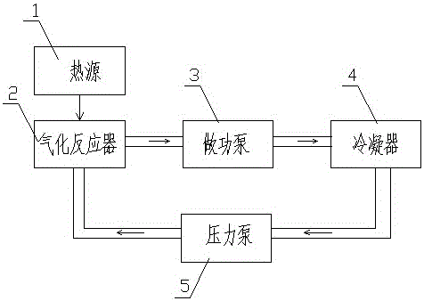
[0097] Embodiment one (such as figure 1 Shown): a thermal power system that comprehensively utilizes the waste heat of the work pump, including heat source 1, gasification reactor 2, work pump 3, condenser 4, pressure pump 5 and circulation pipeline 6, gasification reactor 2, work pump 3. The condenser 4 and the pressure pump 5 realize circulation and communication through the circulation pipe 6, and the gasification reactor 2 is in contact with the heat source 1;

[0098] As a specific description of the above implementation process, the heat source 1 adopts medium-high temperature gas.

[0099] As a specific description of the above implementation process, the gasification reactor 2 includes a layer of cavity 21; the cavity 21 is elliptical.

[0100] As a specific description of the above implementation process, the working pump 3 is an impeller working pump.

[0101] As a specific description of the above implementation process, the condenser 4 is an air-cooled condenser....

Embodiment 2

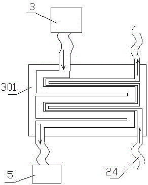
[0105] Embodiment two (such as figure 2 shown): The difference from Example 1 is that: the front end of the gasification reactor 2 is also provided with a preheating chamber 24, and the outlet of the working pump 3 is provided with a precondensation chamber 301, and the preheating The chamber 24 is in parallel contact with the pre-condensation chamber 301; the preheating chamber 24 is in spiral contact with the pre-condensation chamber 301; 1. A flow rate display meter 241 is installed at both ends of the outlet; a flow control valve 242 is also arranged in the preheating chamber 24; the flow-limiting booster valve 242 is an electronically controlled flow control valve.

[0106] With the above structure, since the working medium in the preheating chamber 24 needs to absorb heat, and the working medium in the precondensing chamber 301 needs to discharge heat, this structure recycles the heat of the working medium in the circulation pipeline to a greater extent, increasing the ...

Embodiment 3

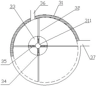
[0108] Embodiment three (such as image 3 shown): The difference from Embodiment 1 is that the working pump 3 includes a circular chamber 31, eccentric blades 32 and a grooved runner 33, and the grooved runner 33 is eccentrically installed on the eccentric shaft 311 of the circular chamber 31 Inside, the side of the grooved runner 33 is provided with a card slot 34, the eccentric blade 32 is installed in the card slot 34 through a spring leaf 35, and the sides of the circular cavity 31 are respectively provided with an air inlet 36 and an air outlet 37, and the air inlet The spacing angle between mouth 36 and air outlet 37 is greater than the spacing angle between adjacent two eccentric blades 32; The pitch angle between two adjacent eccentric blades 32; the eccentric blades 32 of the working pump 3 include four pieces.

[0109] Adopt above-mentioned structure, form isolated chamber between adjacent eccentric blades 32, and what communicate with air inlet 36 is expansion cham...


PUM


Abstract

The invention discloses a heat energy power system comprehensively utilizing waste heat of an acting pump. The heat energy power system comprises a heat source, a gasification reactor, the acting pump, a condenser, a pressure pump and a circulation pipeline. Cyclic communication of the gasification reactor, the acting pump, the condenser and the pressure pump is achieved through the circulation pipeline. The gasification reactor makes contact with the heat source. A preheating cavity is further formed in the front end of the gasification reactor. A pre-condensation cavity is formed in the position of an exhaust port of the acting pump. The preheating cavity and the pre-condensation cavity make contact with each other in parallel. According to the heat energy power system comprehensively utilizing waste heat of the acting pump, the pressure difference between an air inlet and the exhaust port of the acting pump can be increased, and the converting efficiency of a turbine is improved; and meanwhile, the heat of working media in the circulation pipeline is comprehensively utilized, and the heat conversion efficiency is improved.

Description

technical field [0001] The invention belongs to the field of energy utilization equipment, in particular to a thermal energy power system for comprehensively utilizing waste heat of a power pump. Background technique [0002] Energy is an important material basis for the survival and development of human society. Throughout the history of the development of human society, every major progress of human civilization is accompanied by the improvement and replacement of energy. The development and utilization of energy has greatly promoted the development of the world economy and human society. [0003] However, with the continuous development and consumption of energy, non-renewable energy sources such as petroleum, coal mines, and natural gas are gradually reduced, and energy conservation and recycling are gradually being valued. In response to the national energy-saving strategy, more and more enterprises have begun to develop and use energy-saving equipment, and strengthen...

Claims


Application Information

Patent Timeline
Patent Type & Authority Applications(China)
IPC IPC(8): F01K25/08F01K25/10F01K11/00F01C1/344H02N11/00F28B1/06B01D1/00
CPCF01K25/08B01D1/00F01C1/3446F01K11/00F01K25/10F01K25/106F28B1/06H02N11/002
Inventor 郭远军
Owner 郭远军
Why Eureka
Try Eureka