
Air-drive oil extraction method including injecting air into an oil reservoir and increasing the temperature through oxygen-rich oil cracking and electromagnetic wave

A technology of air injection and electromagnetic wave, applied in the fields of fluid production, earthwork drilling, wellbore/well components, etc., can solve the problem of not effectively increasing the energy of oxidative cracking of oil reservoirs, prevent safety accidents, speed up oil production, Guaranteed effect of safe operation

Active Publication Date: 2016-12-14
中嵘能源科技集团有限公司
View PDF12 Cites 8 Cited by
  • Summary
  • Abstract
  • Description
  • Claims
  • Application Information

AI Technical Summary

Problems solved by technology

[0006] Both of the above two oil recovery methods use the combination of air injection and oxygen enrichment for oil recovery, and ignite after injecting oxygen enrichment, but neither of these two methods use combustion aids and downhole electromagnetic wave high temperature steam generators to increase the temperature and pressurize, and cannot Effectively increase the energy of oil reservoir oxidative cracking

Method used


Image

  • Air-drive oil extraction method including injecting air into an oil reservoir and increasing the temperature through oxygen-rich oil cracking and electromagnetic wave

Examples


Embodiment 1

[0032] The present invention provides a method of injecting air into the oil reservoir, cracking oxygen-enriched oil and increasing the temperature by electromagnetic wave and air flooding. The location of the gas injection well is the original water injection well for secondary oil recovery. The specific implementation process is as follows:

[0033] Step 1. Complete the gas injection well and perform re-perforation. The perforation position is selected to be 2 meters in the lower part of the reservoir and 2.5 meters in the middle and upper parts. 102 gun series and 127 perforating bullets are used to penetrate the cement plugging layer and the perforation density Choose 20 holes / m;

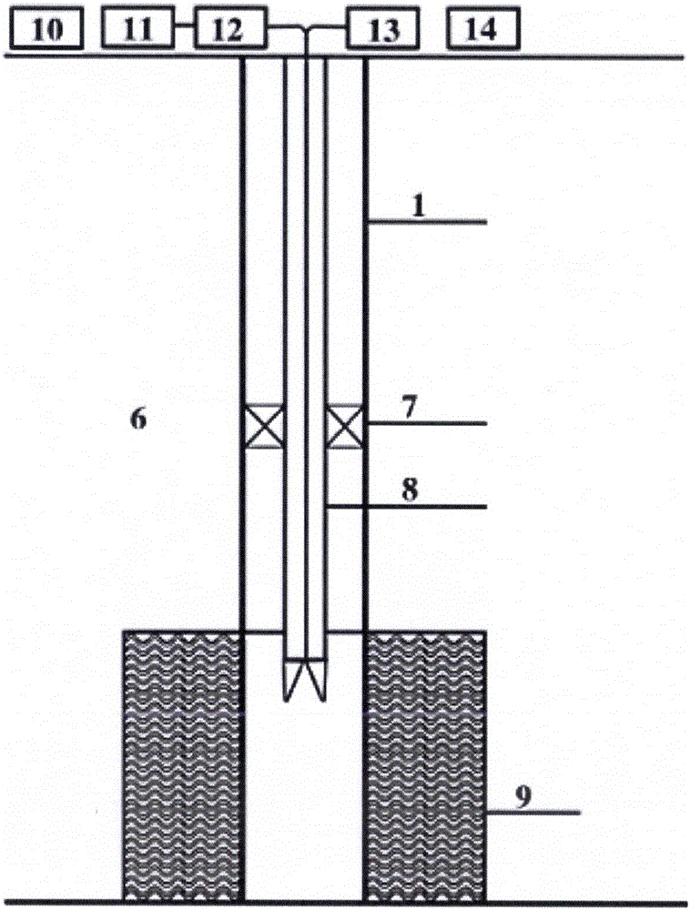
[0034] Step 2. Inject a combustion aid (9) into the oil layer, i.e. 1 ton of ammonium nitrate and potassium chloride mixture with a mass ratio of 1:2, then inject 15,000 standard square meters of air, and then inject 0.5 tons of oxalic acid;

[0035] Step 3. Use the nitrogen separator (10) to de...

Embodiment 2

[0038] The present invention provides a method of injecting air into the oil reservoir, cracking oxygen-enriched oil and increasing the temperature by electromagnetic wave and air flooding. The location of the gas injection well is the original water injection well for secondary oil recovery. The specific implementation process is as follows:

[0039] Step 1. Complete the gas injection well and perform re-perforation. The perforation position is selected as 3 meters in the lower part of the reservoir and 2 meters in the upper part. 102 gun series and 127 perforating bullets are used to penetrate the cement sealing layer and the perforation density is selected. 25 holes / m;

[0040] Step 2. Inject a combustion aid (9) into the oil layer, i.e. 1.5 tons of ammonium nitrate and potassium chloride mixture with a mass ratio of 1:3, then inject 20,000 square meters of air, and then inject 1 ton of oxalic acid;

[0041] Step 3. Use a nitrogen separator to denitrify the air to generate ...

Embodiment 3

[0044] The present invention provides a method of injecting air into the oil reservoir, cracking oxygen-enriched oil and increasing the temperature by electromagnetic wave and air flooding. The location of the gas injection well is the original water injection well for secondary oil recovery. The specific implementation process is as follows:

[0045] Step 1. Complete the gas injection well and perform re-perforation. The perforation position is selected as 5 meters in the middle and lower part of the reservoir. 102 gun series and 127 perforating bullets are used to penetrate the cement plugging layer. The perforation density is selected as 25 holes / m;

[0046] Step 2. Inject a combustion aid (9) into the oil layer, i.e. 1.6 tons of ammonium nitrate and potassium chloride mixture with a mass ratio of 1:2, then inject 25,000 standard square meters of air, and then inject 0.8 tons of oxalic acid;

[0047] Step 3. Use a nitrogen separator to denitrify the air to generate oxygen-...


PUM


Abstract

The invention provides an air-drive oil extraction method including injecting air into an oil reservoir and increasing the temperature through oxygen-rich oil cracking and electromagnetic wave. The air-drive oil extraction method includes: 1, performing well completion on a gas-injection well, and performing re-perforation; 2, injecting a mixture of ammonium nitrate and potassium chloride into an oil layer, injecting air into the oil layer, and injecting oxalic acid into the oil layer; 3, performing denitrification on air through a nitrogen gas separator (10) so as to generate oxygen-rich gas, pulse-injecting the oxygen-rich gas into the oil layer, and performing spontaneous ignition; and 4, alternatively using an underground electromagnetic wave high temperature steam generator (14) to heating and pressurizing the oil layer after spontaneous ignition is successful, and performing continuous air-injection extraction on the oil layer. According to the method, spontaneous ignition is performed by adding a combustion improver and injecting high temperature oxygen-rich mixed gas, the underground electromagnetic wave high temperature steam generator is alternatively used to heat and pressurize the oil layer, and then underground oxidation cracking is accelerated, and the temperature and the pressure is increased greatly. The method is suitable for oil reservoir with the oil layer thickness of more than 2 meters, the permeability of more than 2 MD, and the burial depth of 300-5000 meters, and the method can be applied to vertical wells, horizontal wells, SAGD, and shallow sea oil platforms.

Description

technical field [0001] The invention relates to an air-flooding oil recovery method of injecting air into a reservoir, cracking oxygen-enriched oil and increasing temperature with electromagnetic waves, and belongs to the field of air-flooding oil recovery. Background technique [0002] Most of the oil recovery methods in various countries and oilfields today are mainly water flooding and steam flooding. In the later stages of water flooding and steam flooding, excessive water content, ineffective water circulation, and insufficient formation energy will occur. Air flooding technology can be applied to water flooding. The difference between wells with low flooding efficiency, shut-down wells, and semi-shutdown wells, etc. compared with other oil recovery methods is that after the air enters the oil layer, oxygen reacts with crude oil to crack the crude oil, and the macromolecular chains are broken to form small molecules. The heavy cracking decomposes into various aromatic h...

Claims


Application Information

Patent Timeline
IPC IPC(8): E21B43/16E21B43/22E21B43/243E21B43/24
CPCE21B43/16E21B43/168E21B43/24E21B43/243
Inventor 邓晓亮洪兆
Owner 中嵘能源科技集团有限公司
Learn More