
Negative pressure cleaning system for the cooler of the vacuum system of the auxiliary extruder of the film production line

A vacuum system and negative pressure cleaning technology, applied in the field of negative pressure cleaning system, can solve the problems of too many human resources for machine repair, affecting production efficiency, increasing downtime, etc., to reduce manual cleaning labor, increase cooling work area, and improve cooling. efficacy effect

Active Publication Date: 2018-08-03
ANHUI GUOFENG PLASTIC
View PDF5 Cites 0 Cited by
  • Summary
  • Abstract
  • Description
  • Claims
  • Application Information

AI Technical Summary

Problems solved by technology

When cleaning the cooler, it is time-consuming and laborious. It takes 2-3 hours for a mechanic to clean a cooler. Even if four mechanic clean up four coolers at the same time, it will take 2-3 hours to complete the cleaning.
To clean the cooler of the vacuum system, the production line must be shut down. There are only four maintenance personnel in the day shift of the PET production line, which takes up a lot of maintenance manpower resources and takes a long time to clean up, which increases downtime and affects production efficiency.

Method used

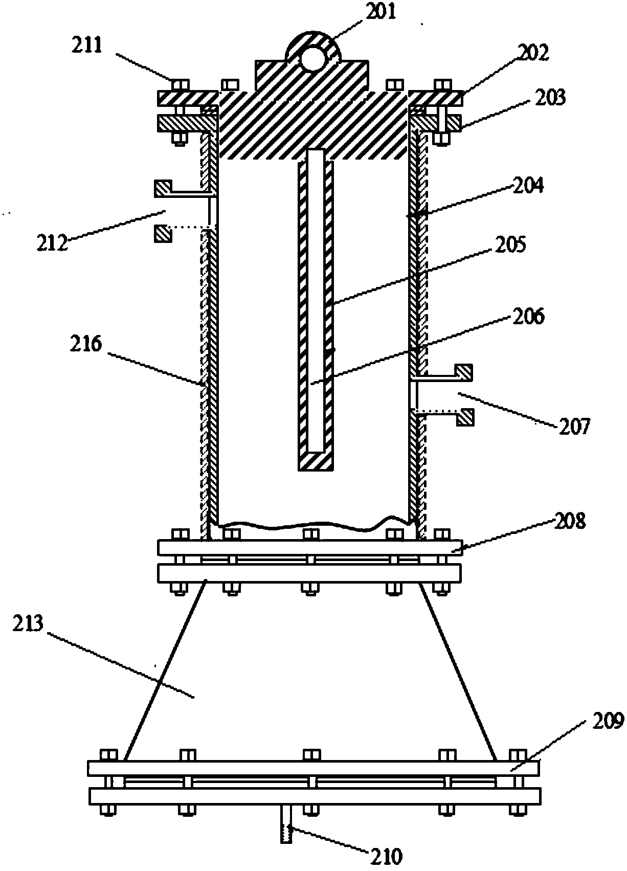
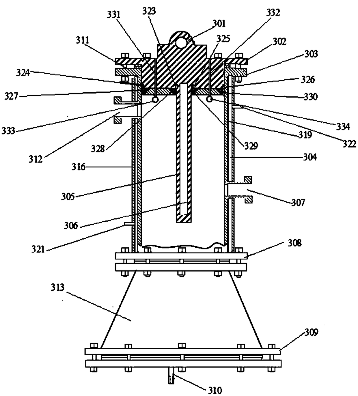

Image

  • Negative pressure cleaning system for the cooler of the vacuum system of the auxiliary extruder of the film production line
  • Negative pressure cleaning system for the cooler of the vacuum system of the auxiliary extruder of the film production line
  • Negative pressure cleaning system for the cooler of the vacuum system of the auxiliary extruder of the film production line

Examples


Embodiment Construction

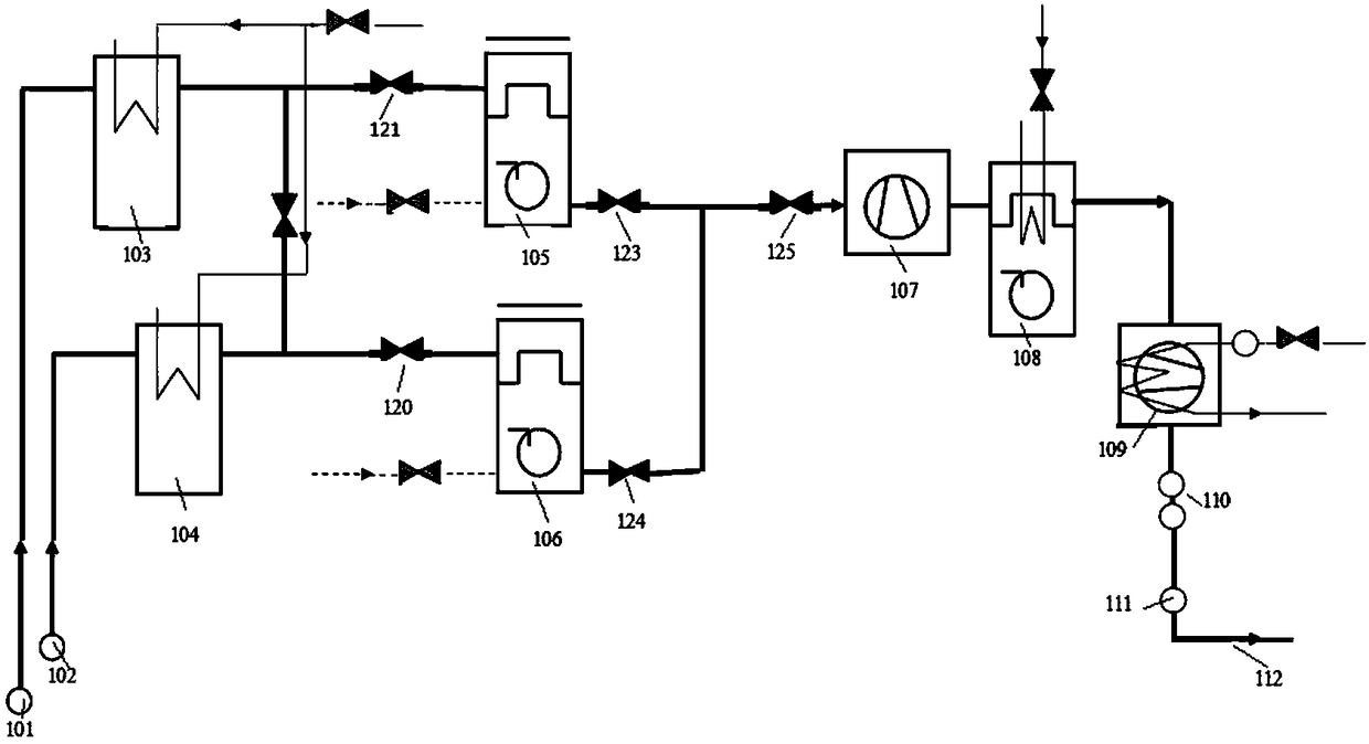
[0022] refer to figure 1 The working principle diagram of the vacuum system of the existing PET film auxiliary extruder is shown, and the working process is as follows: at a working temperature of 270°C, ethylene terephthalate is volatilized from the melted material, and small molecules and water The mixed gas with steam as the main component is cooled by vacuum cover 1 101 and vacuum cover 2 102 through the active heat preservation connecting pipes that are electrically heated to 160°C, and then enters cooler 1 103 and cooler 2 104 for cooling. The active insulation connecting pipe heated to 120°C and the solenoid valve 121 and solenoid valve 120 respectively enter the filter one 105 and the second filter 106, the cross-sectional area of ​​the filter channel increases suddenly, the flow velocity slows down, and the filter has no heat preservation measures. The mixed gas is naturally cooled, and the temperature drops further, the small molecules in the mixed gas condense into ...


PUM


Abstract

The invention relates to a negative-pressure cleaning system used for a cooler of an auxiliary extruder vacuum system of a film production line. The negative-pressure cleaning system comprises the cooler, a filter, a first liquid level tank, a pump and a second liquid level tank; a liquid discharge tube of the cooler is connected to the filter through a first solenoid valve; the filter is connected to the first liquid level tank through a second solenoid valve; the first liquid level tank is connected to an inlet of the pump through a pump-in solenoid valve; an outlet path I of the pump is connected to the second liquid level tank through a pump-out solenoid valve; another outlet path I of the pump is connected to a liquid spray hole in a flange end cover through a liquid spray solenoid valve and a liquid spray flow regulating valve in sequence; the second liquid level tank communicates with an inner cavity of a cooler main body through a communication solenoid valve; and an outlet path I of the second liquid level tank is connected to the filter through an overflow solenoid valve, and another outlet path II of the second liquid level tank is connected to a liquid dropping and filling hole in the flange end cover through a dropping and filling solenoid valve and a dropping and filling flow regulating valve. The negative-pressure cleaning system can keep the cooling working surface of the cooler to be relatively clean, can keep cooling efficiency to be relatively stable, and has a self-cleaning function, so that manual labor amount is reduced.

Description

technical field [0001] The invention relates to a film production line, in particular to a negative pressure cleaning system for the cooler of the vacuum system of the auxiliary extruder of the film production line. Background technique [0002] At present, the known PET film production line auxiliary extruder vacuum system is made up of vacuum cover, cooler, filter, Roots fan, oil-water separator, screw pump, connecting pipe and electromagnetic valve. At the working temperature of 270°C in the auxiliary extruder system, the ethylene terephthalate melt is volatilized, and the mixed gas with small molecules and water vapor as the main components is heated by the vacuum cover of the vacuum system through electric heating. The active insulation connection pipe to 250°C enters the cooler for cooling, and the cooled mixed gas enters the filter through the active insulation connection pipe and electromagnetic valve that is electrically heated to 180°C, and the cross-sectional area...

Claims


Application Information

Patent Timeline
Patent Type & Authority Patents(China)
IPC IPC(8): B29C47/08B29C47/76B29L7/00B29C48/76
CPCB29C48/25B29C48/27B29C48/763B29L2007/00
Inventor 陈庆
Owner ANHUI GUOFENG PLASTIC
Learn More